XGB Analog edition manual
15 - 46
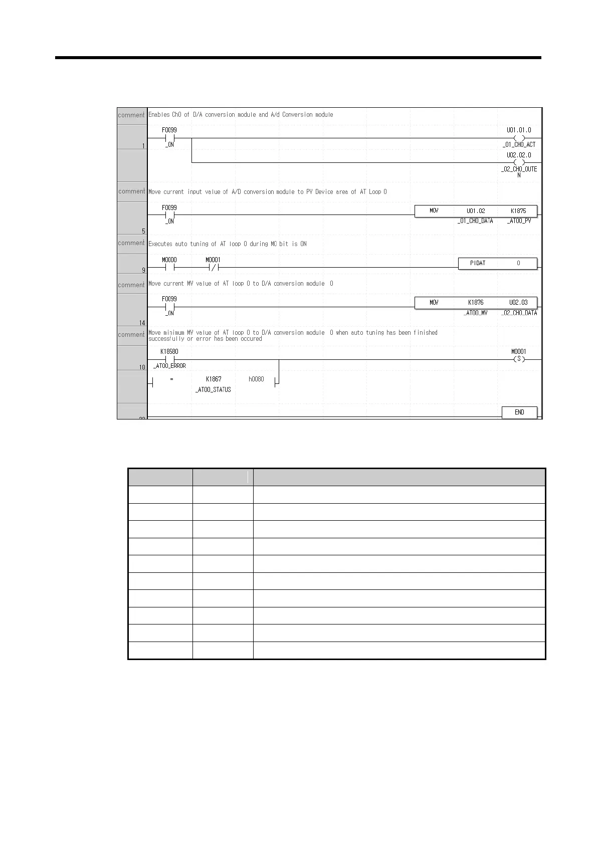
4) Example of PID Auto-tuning program
The example of PID auto-tuning program is illustrated as Figure 15.21.
< Figure 15.21 Auto-tuning example program >
(a) Devices used
It is always on, so it readily operates once PLC is RUN.
It starts operation of CH0 of Slot 1 A/D input module.
It starts operation of CH0 of Slot 2 D/A output module.
PV entered to A/D input module.
MV entered to D/A output module.
Device to which PV is entered for LOOP 0 auto-tuning
Device to which auto-tuning MV of LOOP 0 is output.
Junction that is on once auto-tuning is complete.
Junction that is on once auto-tuning has an error.
Min. MV of auto-tuning designated in parameter.
(b) Program explanation
1) Since F0099(always on) is ON if PLC is converted form STOP to RUN, CH0 of A/D and D/A
starts operating.
2) At the moment, PV entered to CH0 is moved to K1875, the input device of PV and saved
accordingly.
3) Once M0000 junction is on, the auto-tuning of loop 0 starts.
4) The auto-tuning MV of loop 0 that is output by PIDAT command is output to D/A output
module by line 14 MOV command.
 Loading...