Chapter 2 Analog Input Module (XBF-AD04A)
2 - 29
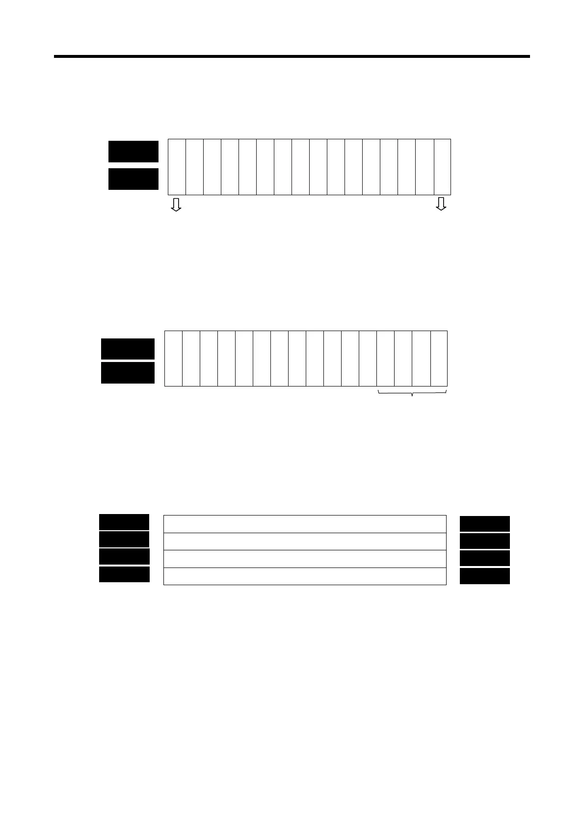
(1) Module Ready/Error flag (U0x.00, x: slot number)
(a) U0x.00.F
: It will be ON when PLC CPU is powered or reset with A/D conversion ready to
process A/D conversion.
(b) U0x.00.0
: It is a flag to display the error status of A/D conversion module.
(2)
Run channel flag (UXY.01, X: Base No., Y: Slot No.)
The area where Run information of respective channels is saved
* XGB series base number is 0
(3) Digital output value (UXY.02 ~ UXY.09, X: Base No., Y: Slot No.)
(a) A/D converted-digital output value will be output to buffer memory addresses UXY.02 ~
UXY.05 (%UW0.x.2 ~ %UW0.x.5) for respective channels.
(b) Digital output value will be saved in 16-bit binary.
※ XGB PLC’s base number is 0.
B15 B14 B13 B12 B11 B10 B9 B8 B7 B6 B5 B4 B3 B2 B1 B0
Channel 0 digital output value
Channel 1 digital output value
Channel 2 digital output value
Channel 3 digital output value
Bit15 Bit14 Bit13 Bit12 Bit11 Bit10 Bit9 Bit8 Bit7 Bit6 Bit5 Bit4 Bit3 Bit2 Bit1 Bit0
Ready
— — — ———————————
Error
B15 B14 B13 B12 B11 B10 B9 B8 B7 B6 B5 B4 B3 B2 B1 B0
—— — — ————————
C
H
3
C
H
2
C
H
1
C
H
0
Error status
Bit On (1): error, Bit Off (0): normal
U0x.00
Module READY
Bit On (1): normal, Bit Off (0): error
Run channel information
Bit ON (1): During Run, Bit Off (0): Operation Stop
UXY.01
(UW0.x.0)
(%UW0.x.1
2
x.
2
x.
x.
4
x.
W
.x.2
W
.x.
W
.x.4
W
.x.
 Loading...