Lucent Technologies Galaxy Power System 4812
12 - 10 Troubleshooting Preparations Issue 5 June 2000
Reference Figures, continued
Low Voltage
Battery Disconnect
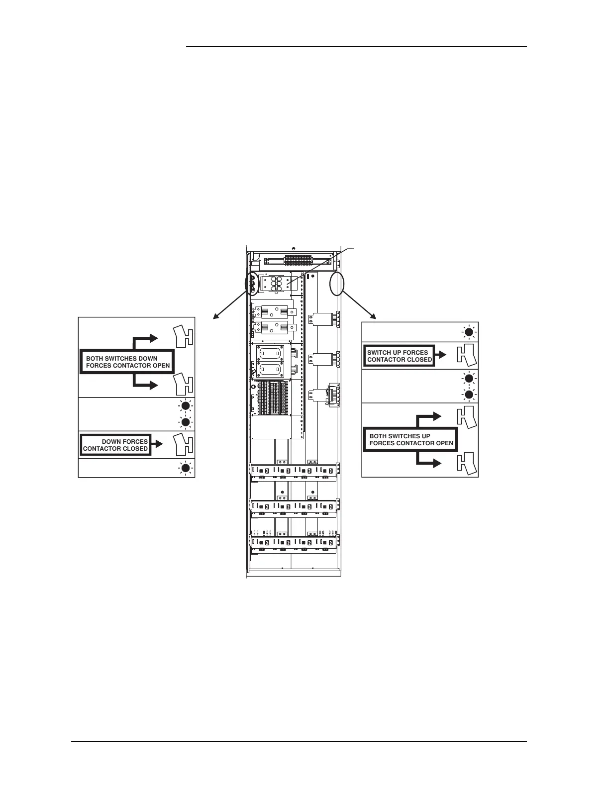
The low voltage battery disconnect (LVBD) feature consists of a
contactor, circuitry on the BJN board, and associated wiring. Control of
the contactor is dictated by the BJN contactor control board and the
controller.
Figure 12-7 shows the location of the contactor control board in the GPS
cabinet.
Figure 12-7: Low Voltage Battery Disconnect Contactor
Control Switches
Red Light
Yellow Light
Green Light
CONTACTOR DRIVE BOARD
SW
SW
SW
BOTH SWITCHES DOWN
FORCES CONTACTOR OPEN
CONTACTOR OPEN
CONTACTOR OPEN INITIATED
DOWN FORCES
CONTACTOR CLOSED
REMOTE CONTROL ENABLED
Red Light
Yellow Light
Green Light
SW
SW
SW
BOTH SWITCHES UP
FORCES CONTACTOR OPEN
CONTACTOR OPEN
CONTACTOR OPEN INITIATED
SWITCH UP FORCES
CONTACTOR CLOSED
REMOTE CONTROL ENABLED
Note: All switches should be in the
down position for normal operation
Note: All switches should be in the
up position for normal operation.
Control card mounted
on right side of cabinet.
Control card mounted
on left side of cabinet.
Typical Battery Panel