Lucent Technologies Galaxy Power System 4812
Issue 5 June 2000 Troubleshooting Preparations 12 - 13
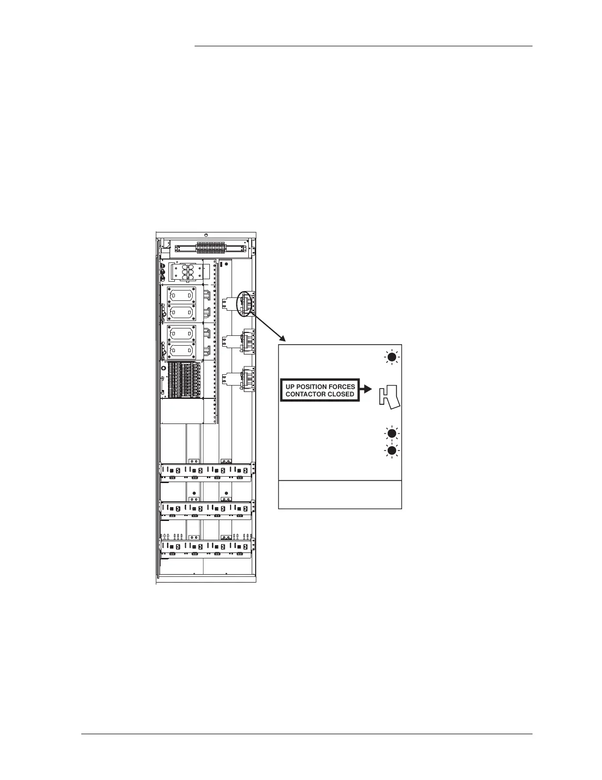
Reference Figures, continued
Low Voltage Load
Disconnect
The EBV low voltage load disconnect (LVLD) contactor control board
is mounted on the right side of the cabinet, as shown in Figure 12-10.
The manual contactor control switch (SW300) is not meant to be used
to permanently override the LVLD function. It is only to be used
temporarily while servicing or testing the equipment.
Figure 12-10: Low Voltage Load Disconnect Contactor
Control Switches
Note: Switch should be in the
down position for normal operation.
Red Light
Yellow Light
Green Light
UP POSITION FORCES
CONTACTOR CLOSED
REMOTE CONTROL
ENABLED
CONTROLLER SIGNAL
ERROR DETECTED
CONTROLLER SIGNAL
OPENED CONTACTOR
GREEN LIGHT
YELLOW LIGHT ONLY
RED AND YELLOW LIGHT
LOAD DISCONNECT FEATURE IS NOT
FOR USE IN BATTERYLESS SYSTEMS
REMOTE
CONTROL
OVERRIDE
SWITCH
Control switch mounted
on right side of cabinet.