Lucent Technologies Lineage
®
2000 ECS-12U Controller J85501E-2
2 - 4 Product Description Issue 3 July 1998
Basic
Controller
The basic ECS-12U controller monitors and controls any
combination of up to twelve Lucent Technologies switchmode
(SR) or ferroresonant rectifiers and provides a single interface
point for power alarm and status reporting. Equipped with a
113B Control Unit, two RIBs, and an LVD/Fuse Board or Fuse
Alarm Board, the basic controller performs the traditional
analog control functions of the MCS, CCS, or XCS controllers.
Each of these functions is described in detail in the paragraphs
that follow.
Operating
Voltage
The controller is powered by the plant dc voltage and may be
used in 24V or 48V plants. It may be powered from either
positive ground systems, e.g., -48V, or negative ground systems,
e.g., +24V. Movable jumpers located on the upper backplane
and DIP switches located on the 113B and the Rectifier Interface
Boards (RIB) must be positioned according to the plant voltage.
The 113B may be plugged directly into the ECS-12U controller
when the backplane is properly configured.
Batteryless
Operation
The ECS-12U controller is suitable for telecommunications
power plants with or without batteries. In batteryless plants, the
loss of ac power causes an immediate loss of dc power to the
controller. When ac power is restored, the ECS-12U controller,
in an unpowered state, allows the rectifiers to automatically
restart.
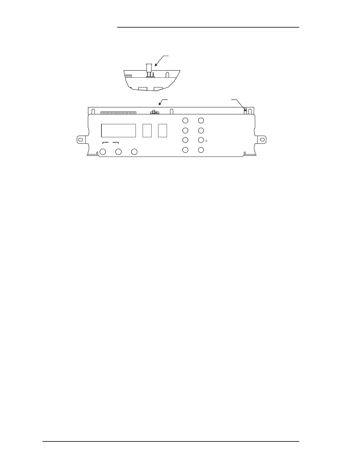
Figure 2-3: Detail of 113B Control Unit Display Panel
OUTPUT VOLTS
AMPS
NORM
V
+–
EQ
FLOAT
BD
ACF
MNF
EQ DLA
RFA
MJF
P
SW409
VOLTS FLOAT
P401
R407
DEC
DEC
NO DEC
NO DEC