Lucent Technologies Lineage
®
2000 ECS-12U Controller J85501E-2
Issue 3 July 1998 Installation and Setup 4 - 13
Optional
Rectifier Adapter
Board (RAB)
Adding the Rectifier Adapter Board (RAB) to the controller
extends the features described in this manual to non-Lineage
rectifiers either manufactured by Lucent Technologies or
manufactured for Lucent Technologies to a J or KS
specification. The RAB also enables the use of non-Lucent
Technologies rectifiers. DIP switches S1 through S6 on the RAB
must be set corresponding to rectifier ports 1-6 for the lower
RAB and rectifier ports 7-12 for the upper RAB for each
non-Lineage rectifier connected to the controller. Figure 4-10
shows this table of settings. These settings are also on a label on
the inside of the controller door. If a rectifier is added after initial
installation, it may be necessary to remove the RAB to access
DIP switches. Alarms to rectifiers requiring the RAB will not
function properly until the RAB is reinstalled. Always notify
the Alarm Center before working on the controller.
Table 3-B lists the cables required for the various rectifiers.
Those rectifiers not listed will require a termination either to a
screw or wire wrap terminal at the rectifier end of control cable
H285-226, L45. See Table 4-C and Figure 4-11.
NOTES The rectifier must have a feature in order for the ECS-12U
to extend that feature to the system. For example, if a
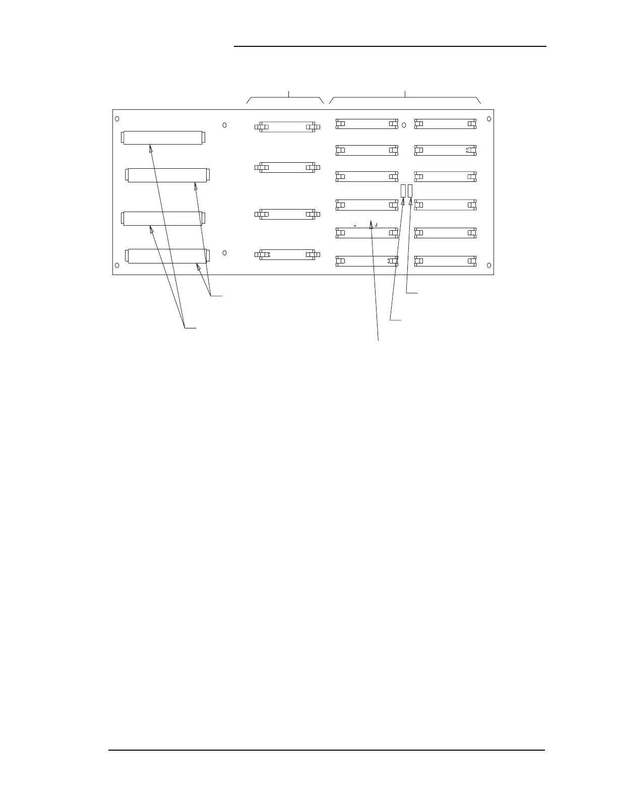
Figure 4-8: ECS-12U Controller Backplane (Lower)
Multiplexer Board
Connections to Rectifiers
EAT2
EAT2
EAT1
EAT1
J713-4
J713-3
J713-2
J713-1
J714-2
J714-1
J714-4
J714-3
RECTIFER 12 RECTIFER 9
RECTIFER 8
RECTIFER 7
RECTIFER 3
RECTIFER 2
RECTIFER 1
RECTIFER 11
RECTIFER 10
RECTIFER 6
RECTIFER 5
RECTIFER 4
J704 J701
Connections to 248A Order Wire
Connections to AKC1B Shunt Isolator
Slots for RIB
Slots for RAB
J702
J703
J707
J715J716
J708
J709
J705
J706
J710
J711
J712