Lucent Technologies Lineage
®
2000 ECS-12U Controller J85501E-2
Issue 3 July 1998 Installation and Setup 4 - 3
Jumper straps are located on the upper tray backplane, and a
combination of jumper straps and DIP switches are located on
the 113B control unit and the rectifier interface board (RIB).
These jumpers and switches must be set properly before
powering the controller. Proper settings are made at the factory
for the plant in which the controller is shipped. In shipped-loose
controllers, the jumpers and switches are factory configured for
-48 volt operation for List 1or 3 and +24 volt operation for List 2.
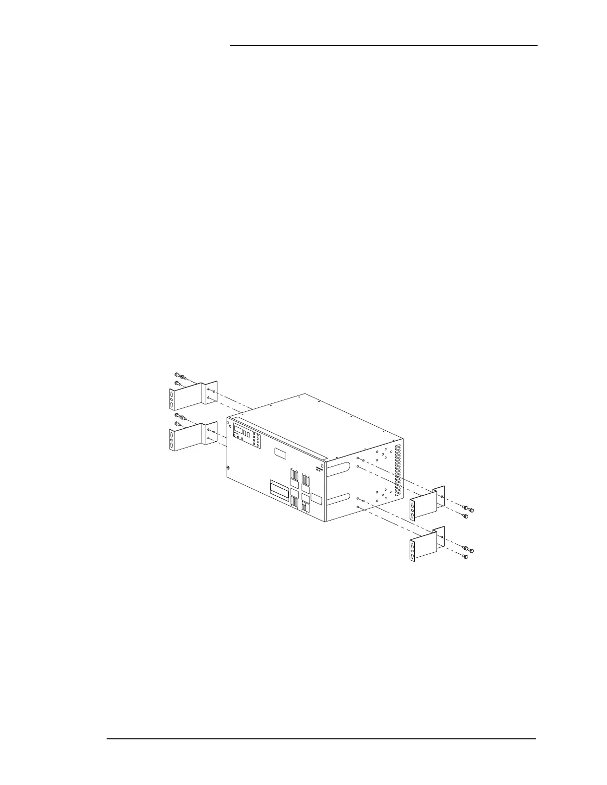
Frame Mounting The controller is equipped with four mounting brackets for
installation in battery plants with a 26-inch framework. Refer to
Figure 4-1. The brackets position the controller flush with the
front of the framework. Extra mounting holes allow installers to
move the brackets back 3-1/2 or 5 inches for applications where
equipment extends 3-1/2 or 5 inches from the framework.
Alternative mounting brackets are provided per J85501E-2 List
BA for installation in a 23-inch framework. Refer to Figure 4-2.
These brackets may be also relocated in the field.
Figure 4-1: 26-inch Frame Mounting
LucentTechnologies
LucentTechnologies