Lucent Technologies Lineage
®
2000 ECS-12U Controller J85501E-2
Issue 3 July 1998 Installation and Setup 4 - 17
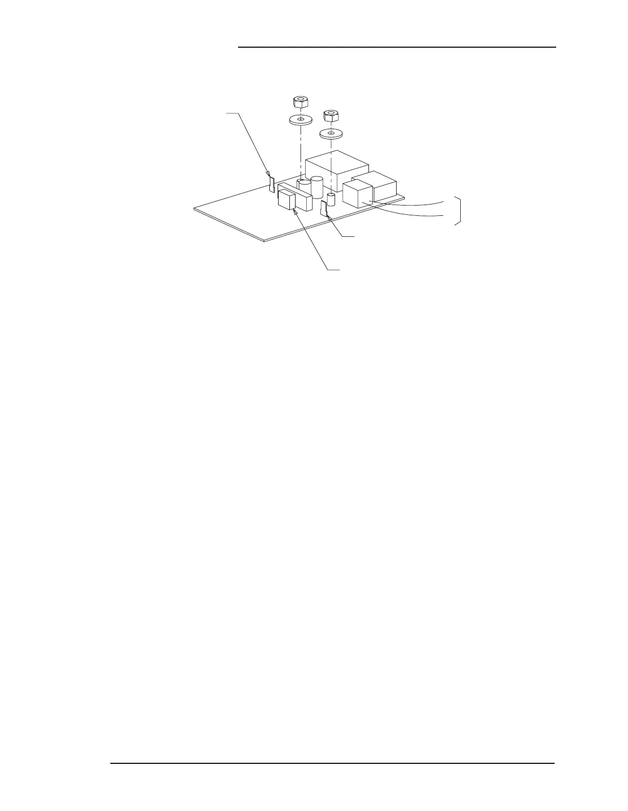
Optional 248A
Order Wire Board
The Order Wire Board interface feature shown in Figure 4-12 is
optional for the plant. This feature should be ordered when the
plant will be monitored over the FT-Series G or a similar
embedded maintenance system. Additional equipment and
connections are required outside the power bay to establish the
communication link over the FT-Series G embedded telemetry
system.
For each repeater site, an SM535 circuit pack (J98764R-1, L45)
is required for order wire slot 4 of each Line Repeater Bay
(LRB). An SM534 (J98764T-1, L15) circuit pack is also
required at the terminal site(s) of each route.
The external connections in Table 4-D are required at the back
of the LRB and TCC (Telemetry Channel Control) in order to
establish a communication link with the ECS-12U Controller
over the FT-Series G embedded maintenance system (slot 4 is
most commonly used).
Refer to the FT Series G Lightwave Systems Battery Plant
(H569-367) product manual for more information about the
installation and use of this option.
Figure 4-12: 248A Order Wire Board
E6-TO DISCHARGE BATTERY
VIA WIRE KIT 846832343
P13 - ORDER WIRE SIGNAL LEADS
TO P10 OF ALARM INTERFACE
PANEL, ED-83227-30, VIA
WIRE SET SET 845653765
E5 - TO GROUND VIA
WIRE KIT 846832343
TO J203 ON CP2 OF
ECS CONTROLLER VIA
TELEPHONE CORD
(106595684)
2
J12
3