Lucent Technologies Lineage
®
2000 ECS-12U Controller J85501E-2
4 - 20 Installation and Setup Issue 3 July 1998
the switch settings in Tables 4-G and 4-H. Use the following
procedure to reset R48 and R29.
1. With sensing inputs J1-4 and J1-5 either open or shorted
together, verify that the output at J1-7 and J1-8 reads 0.0X
mV (X can be from 1 to 5). If it does not, you may need to
readjust the factory settings of the offset (R48)
potentiometer.
2. Connect the sensing inputs to the shunt, observing proper
polarity (J1-4 to the most negative and J1-5 to the most
positive). Measure the shunt mV drop and calculate the
plant load with the formula: (Full Scale Shunt Amps/Full
Scale Shunt mV) x Shunt mV Reading. Adjust R29 to
obtain this reading on the plant ammeter. Verify a second
time.
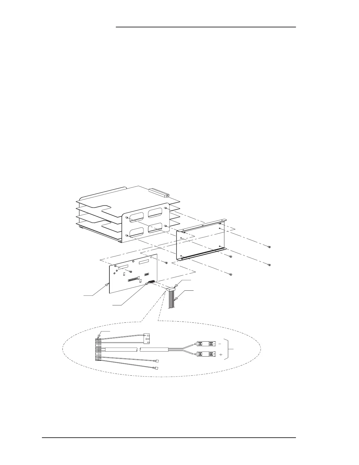
Figure 4-13: Shunt Isolator Circuit
P1
847270022
Wire Set
AKC1B
J1
P1
To J716
on Backplane
Mounts
to Shunt
To TB1-1
To TB1-2
O-BK
O
V
Y
[1]
[6]
BL
W-BL
DS1
SW2
AKC1B
SER X:X
SW1
PS1PS2
DS2
OUTPUT
R29
R48
OFFSET
CALIBRATE
R45