Lucent Technologies Lineage
®
2000 ECS-12U Controller J85501E-2
Issue 3 July 1998 Installation and Setup 4 - 31
3. Unplug the remaining ribbon cable connections to the
board, noting the location of each so that they can be
reconnected later.
4. The multiplexing board is mounted to the chassis by five
screws. The controller chassis can be removed from the
frame if necessary for access to the board.
5. Replace the board and reconnect ribbon cables and ground
wire as they were.
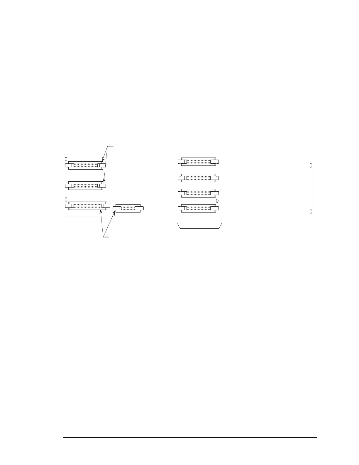
Figure 4-16: Rectifier Multiplexing Circuit Pack
J705
J706
J708
J707
J702
J701
J704
J703
BCC1 PWB
Connections to
Rectifier Shelves
Connections to Backplane
Connections to
LVD/Fuse Board