Lucent Technologies Lineage
®
2000 ECS-12U Controller J85501E-2
Issue 3 July 1998 Installation and Setup 4 - 11
decimal position (DEC); for currents over 999A, place the
jumper or slide switch to the no-decimal position (NO DEC).
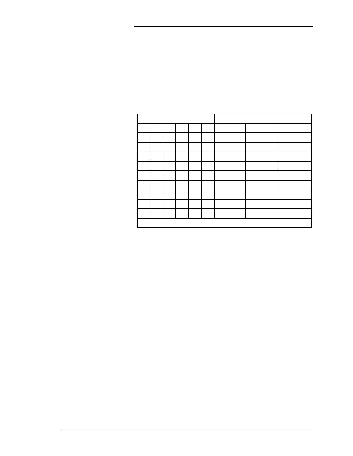
The controller will only work with the shunt sizes listed in Table
4-B. In battery plants with other shunt sizes, replace the shunt or
use an AKC1B circuit pack. When the AKC1B is used, use
Table 4-H instead of Table 4-B to configure SW109.
Battery on
Discharge
Threshold
The voltage threshold for the BD alarms is set with DIP switch
SW103. (See Figure 4-4.) Refer to Figure 4-5 or the label on the
113B cover plate for the DIP switch settings for the desired
alarm threshold. The same table of settings also appears on
schematic drawing SD83181-01 and on the assembly drawing
J85501E-2. The recommended threshold is approximately 1.0
volt below the float voltage for nominal 48-volt plants or
approximately 0.5 volt below float for nominal 24-volt plants.
Be sure to set DIP switch 6 of SW103 for the proper operating
voltage.
High Voltage
Shutdown
Thresholds
The controller is equipped with two separate high voltage
shutdown thresholds. The first is used during normal float
operation. The second threshold is used when the plant is in
equalize mode. The float shutdown is set with DIP switch
SW102 on the 113B. (See Figure 4-4.) The equalize shutdown is
controlled by DIP switch SW101 on the 113B. The equalize
shutdown level does not need to be set if equalize is hardware
disabled (see “Equalize Enable/Disable.”) The recommended
Table 4-B: SW109 DIP Switch Settings
Use These Switch Settings For These Plant Shunt Sizes
Shunt Full Scale Millivolts
123456 25mV 50mV 100mV
cooocc
150A* 300A* 600A*
cooooo
300A* 600A* not usable
ocoooo
600A* 1200A 2400A
oococc
1000A 2000A 4000A
ooocoo
1300A 2600A 5200A
oocooo
2000A 4000A 8000A
cooooo
3000A 6000A not usable
oooooo
4000A 8000A not usable
*Decimal point must be used in these settings.