Lucent Technologies Lineage
®
2000 ECS-12U Controller J85501E-2
Issue 3 July 1998 Installation and Setup 4 - 5
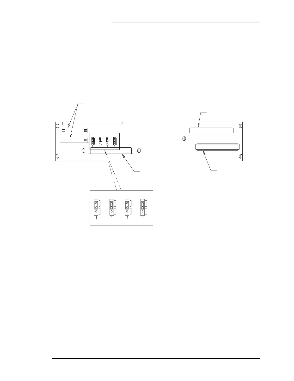
Voltage Selection As shown in Figure 4-3, there are four jumpers for voltage
selection. Verify that all of the jumpers are in the correct
positions. DIP switches SW101, SW102, and SW103 on the
113B, and S1and S2 on the RIB, must be set to the proper plant
voltage. (See Figures 4-4 through 4-7.) DIP switch position 6 on
SW101, SW102 and SW103, and positions 1 thru 10 on S1 and
S2 must be set for either 24 or 48 volts. All of these switches
must be set to the same voltage.
Figure 4-3: ECS-12U Controller Backplane (Upper)
Connection to
Multiplexer Board
CP3 Expansion Slot
CP2 Expansion Slot
Slot for 113B
Control Unit
846575280 PWB ASSEMBLY
SS3
C1 C32
C32
B32
A32
A32
B32
C32
C1
331
1
33
342
2
34
B1
A1
P101
CP1
P602.1
P602.1
P603.1
P603.2
RECTIFIERS 4-5-6
RECTIFIERS 1-2-3
P602.2
P602.2
JUMPER SETTINGS
P602.3
P602.3
P602.4
P602.4
24V 48V
24V 48V
24V 48V
24V 48V
24V 48V
24V 48V
24V 48V
24V 48V
A32
C1
B1
A1
A1
CP2
CP3
P301
P201