ND30-09D 24 User's manual
3_on – when the measuring value on any phase will be between the
"Condition lower value" and "Condition upper value" - condition is true.
The condition will be disabled if the measuring value on all phases will
be below "Condition lower value" or above "Condition upper value".
3_oF – when the measuring value on any phase will be below the
"Condition lower value" or above "Condition upper value" - condition is
true. The condition will be disabled if the measuring value on all
phases will be between the "Condition lower value" and "Condition
upper value".
The alarm value in the series 3 alarms must be in the range: 01-09,
10-18 and 19-27 (acc. to Table 8). They work with identical thresholds
"Condition lower value" and "Condition upper value" for each phase.
The blanking of the alarm signalization latch follows pressing the
buttons and (> 3 sec.).
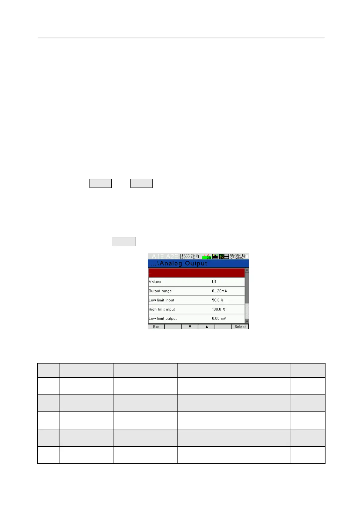
7.4 Analog output mode
In the options, select the Analog output mode and confirm selection by
pressing the button .
Fig.18. Screens of Analog output mode
Table 3
Item Parameter name Feature / value Description Default
settings
1 Value U1, I1,...,T2,
hh:mm
Value on analog output
parameter acc. to Table 8
P
2 Output range 0...20 mA,
4...20 mA,
Analog output range 0...20
mA
3 Low limit input -144.0 .. 144.0% Lower value of the input range in
% of the rated range
0.0
4 High limit
input
-144.0 .. 144.0% Upper value of the input range in
% of the rated range
100.0
5 Low limit
output
00.00 .. 24.00 Lower value of the output range
in mA
0.00
AlarmDel
Select
 Loading...