ND30-09D 26 User's manual
2 Pages color Green
Red
Yellow
:
Olive
Color of displayed
values in Measurement
mode
Green
3 Display field 1 No
Yes
No
4
Page
1
:
:
Page
10
Display field 1
:
:
Display field 8
Off
U1
I1
P1
Q1
:
En S
Selection of displayed
values on a selected
page and selected field
acc. to Table 5.
Table 6a
or 6b or 6c
-
depending
on the
connection
system
5
Page
13
Displayed value Off
U1
I1
:
T2
Selection of the
visualized quantity on
the analogue indicator
according to table 5
U1
Bottom scale
-0144.0 The lower value of the
analog indicator scale
0.0
Upper scale
+0144.0 The upper value of the
analog indicator scale
100.0
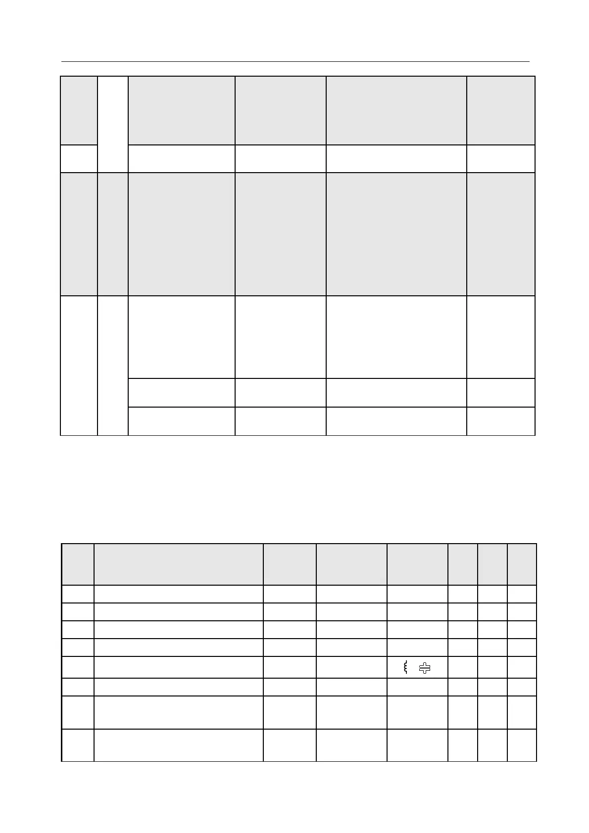
Selection of displayed values:
Table 5
Item Value name Marking Unit Signaling
3Ph
/
4W
3Ph
/
3W
1Ph
/
2W
00 no value - blanked display field
Off
01 L1 phase voltage
U1
(M, k)V
x
02 L1 phase wire current
I1
(k)A
03 L1 phase active power
P1
(G, M, k)W
x
04 L1 phase reactive power
Q1
(G, M, k)var
/
x
05 L1 phase apparent power
S1
(G, M, k)VA
x
06 L1 phase active power factor
(PF1=P1/S1)
PF1
x
07
tg factor of L1 phase
(tg1=Q1/P1)
tg1
x
 Loading...