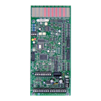
Lighting Relay Panel
Controller User’s Guide
www.lumisys1.com
Due to continuous product improvement, Lumisys reserves the right to change product specications without notice.
Page 10
Number of Relays/Outputs
• This feature provides the capability to limit the number of outputs the LrP Controller will control.
• This value can be between 1-60 outputs (8 for the L28 Series Controller).
• The maximum number of outputs are determined by the LRP Controllers enclosure capacity and the number of outputs
installed in the enclosure
Group On-time After Flash
• Each output that is assigned to ash (see “Output Flash”) before automatically turning off will have an on-time after
ash value of 1-60 minutes in 1 second increments.
• All outputs use the same on-time after ash value per LRP Controller.
Output/Relay Energize Time
• The length of time the outputs coil is energized to change its state is programmable from .024 seconds to 1.56 seconds
in .012 second increments.
• This time is factory set for .072 seconds and typically should not be changed.
Assigning Outputs/Circuits to a Group
• LUMISYS uses a control strategy that requires all outputs to be assigned to one or more groups. Control is
accomplished at the group level so each controlled output needs to be assigned to a group.
• Each LRP Controller provides up to 60 groups
• A group can include one output or many outputs up to the LRP Controller maximum. See table 1 for a listing of
LRP Controllers and their maximum output capacities.
• If an application requires individual control of each output then assign each output to an individual group such as
output 1 to group 1, output 2 to group 2, etc. Many applications require multiple outputs to be turned on or off as a
group. Grouping eliminates the need to have a separate command for each output rather all of the groups outputs can
be controlled with one input or network command.
• If groups share the same output then the shared output will not turn off until all its groups are commanded off. For
instance, a common area lighting circuit may be connected to output 1. If output 1 is assigned to both group 1 and 2
then both groups must be commanded off before the common area lighting will turn off. If group 1 and 2 are on and a
command is issued to turn off group 1, output 1 will remain on because group 2 is on.
• Grouping is performed in the LRP Controller software so no hardwiring of outputs into groups is necessary.
Naming Groups and Super Groups
• Each group and Super Group can be named for identication purposes.
• Requires LP-PK 4.0, Group and Super Group names are saved in the LP-PK .lpx le not in the LRP Controller.
Assigning Groups to Super Groups
• A Super Group is a logical grouping of 2 to 59 groups. The word super is used to differentiate between the two group
types.
• Super Groups provide the capability to control multiple groups with one input or network command yet still allow
individual control of each group.
• For example, Super Group 1 can contain groups 2-5. A network command can be issued to turn off Super Group
1, which will turn off groups 2-5. However, an input assigned to group 4 can turn on group 4 without affecting groups
2,3 or 5. Super Groups provides a high degree of exibility.
• A Super Group can contain any group but the Super Group number itself. Super Group 1 can contain any group but
group 1.
• Super Groups contain two or more Groups.
• Groups containing one or more outputs.

 Loading...