Lighting Relay Panel
Controller User’s Guide
www.lumisys1.com
Due to continuous product improvement, Lumisys reserves the right to change product specications without notice.
Page 6
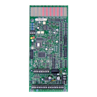
3. System Status LED #1 (top, right) is the heartbeat of the LRP Controller. During normal operation
this LED should be ashing on and off. During programming mode it will be steady on. If this LED is
not ashing during normal operation then there is a potential problem with the LRP Controller. Please
see theTroubleshooting section of this guide.
4. The LRP Controllers will use STATUS LEDs 2-7 to display network communication information. This
is a great feature for technicians to quickly determine network status. The information displayed on
all LRP Controllers is as follows.
· STATUS LED 2 - Illuminates when any serial command is received.
· STATUS LED 3 - Illuminates when end of command character is received.
· STATUS LED 4 - Illuminates when this LRP Controller is addressed.
· STATUS LED 5 - Illuminates when a correct checksum is detected.
· STATUS LED 6 - Illuminates when this LRP Controller receives a legal command.
· STATUS LED 7 - Illuminates when the LRP Controller has executed a command.
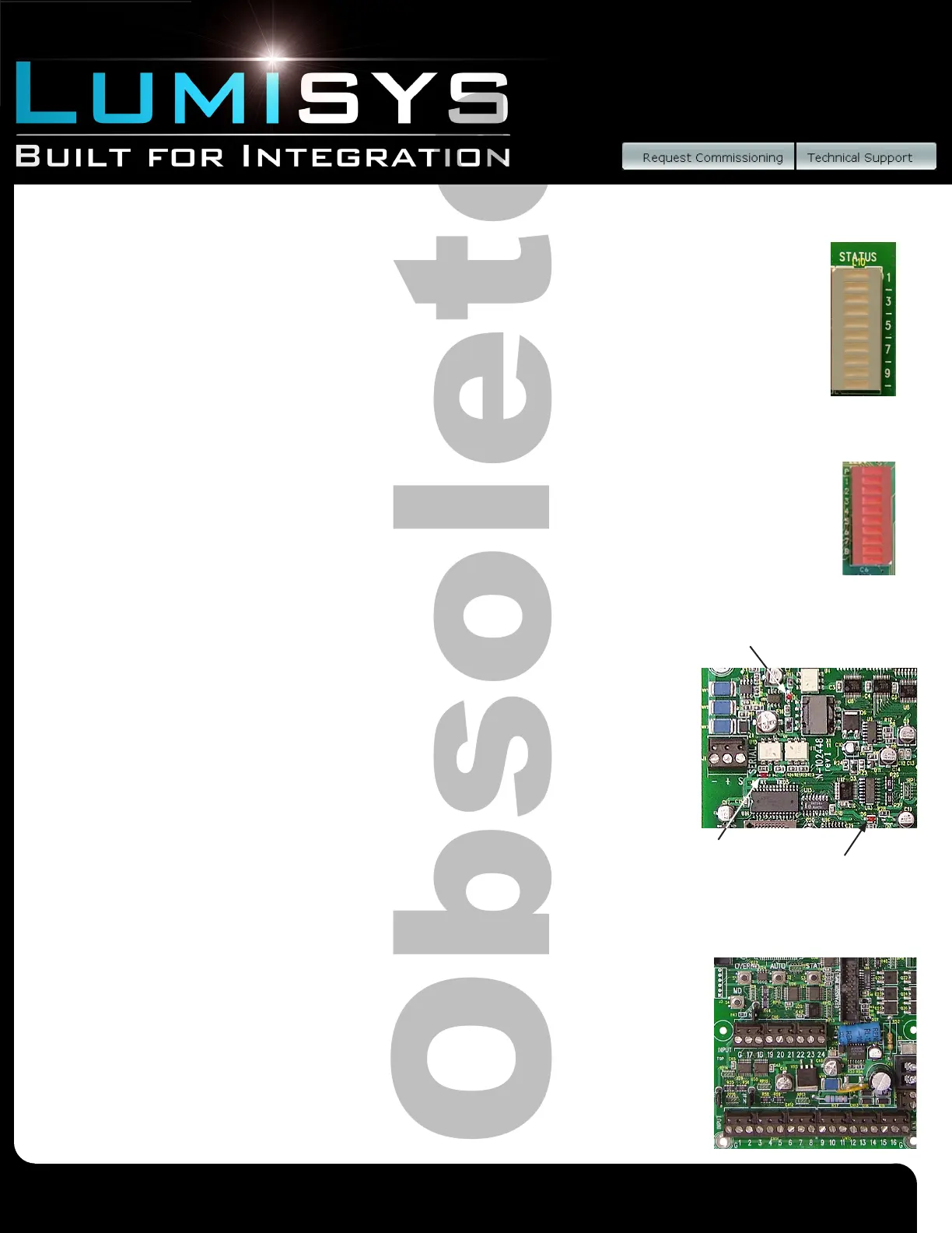
5. LRP Controller L28 Series LED’s indicate either the state of each of its
eight outputs or the network communication information. When in the network
communication mode the LED’s represent the same information as shown
above for STATUS LEDs 2-7. Pressing the STAT Pushbutton will display network
communication information and pressing the AUTO Pushbutton will display the
status of its eight outputs. STATUS LED P on the L28 Series is the watchdog
timer and power indication, and 1-8 represent each of its outputs.
Power, Communication and Watchdog LEDs
6. Power LED is steady on when the proper power is applied to the LRP Controller.
If this LED is not on please see the Troubleshooting section of this user guide
7. Communication TX LED illuminates if the LRP Controller is sending outbound
communication and the RX LED illuminates each time inbound communication
is received. If these LED’s are not operating please see the Troubleshooting
section of this user guide.
8. Watchdog LED should be steady on. If this LED is ashing or off please see
the Troubleshooting section of this guide
Inputs
9. Input terminal blocks for connecting input wiring. The terminal blocks can be
removed from the LRP Controller for easy installation or for quick replacement of a
LRP Controller. 24 inputs standard, expandable to 120 inputs; 16 inputs
maximum for L28 Series.
10. Input expansion connector (Socket) provides connection of up to three optional thirty-two
Input expansion modules (See LEXP Data sheet) per LRP Controller for a total
Power LED
RX & TX
LEDs
Watchdog
LED
See Figure 1
See Figure 1
See Figure 2
See Figure 1
 Loading...