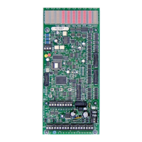
Lighting Relay Panel
Controller User’s Guide
www.lumisys1.com
Due to continuous product improvement, Lumisys reserves the right to change product specications without notice.
Page 7
of 120 inputs. This is not available for the LRP Controller L28 Series.
11. Input Power jumper provides the capability to select the LRP Controller to power its inputs or allow an external
power source to power its inputs. Occupancy sensors that use 24VDC to power the sensor are typical
applications that are externally powering an input. Jumper in the “N” position congures the inputs to be dry
contact and powered by the LRP Controller. Jumper in the opposite position congures the inputs to be
externally powered by up to 24VDC. Each jumper affects only its respective eight inputs only. There is one
jumper for each of the LRP Controller’s eight inputs.
12. Analog Input terminal accepts a VDC signal up to a maximum of 6VDC or LUMISYS’ LS Series Light Sensors
Model LS Series /I-5V-0-5 for indoor level, LS Series /O-5V-0-5 for outdoor light level and LS Series /S-5V-0-5
for skylight levels.
Outputs
13. Output terminals to output devices. The LRP Controller provides cable headers for connection to its outputs.
See TABLE 1 for details on the output capability of each LRP Controller. A ribbon cable is used to connect the
LRP Controller output header to either a Relay Interface Board or Circuit Breaker Interface Board. Each output
driver on the LRP Controller is protected to survive a direct short which minimize failures.
14. On board current limiting is provided on all output drivers.
Pushbuttons
15. Three pushbuttons labeled “OVER” (or CH), “AUTO” (or BK) and “STAT” (or TG)
are provided on the LRP Controller to provide,
1) manually override of all the relays,
2) set the network address of the LRP Controller, and
3) view network status and group and relay status for more information on their use please refer to
the software features section of the user guide.
Power Supply Protection
16. Supply Power terminals for connection of 24VAC power. The terminal block can
be removed from the LRP Controller for easy installation or quick replacement of
an LRP Controller. The LRP Controller supply power protection circuitry provides
30VA self reset over-current protection.
Network Terminals
17. Network communication terminal blocks for connecting network. The terminal
blocks can be removed from the LRP Controller for easy installation or for quick
replacement of an LRP Controller. On-board isolation circuitry provides 500-volt
isolation for the RS-485 communication network.
EPROM and EEPROM Diagnostics
18. The LRP Controller continuously veries integrity of its EPROM (Electrically Programmable-Read Only Memory)
and EEPROM (Electrically Erasable Programmable Read Only Memory). Unit will notify that an error exists through
the LP-PK Set Up software.

 Loading...