Lighting Relay Panel
Controller User’s Guide
www.lumisys1.com
Due to continuous product improvement, Lumisys reserves the right to change product specications without notice.
Page 20
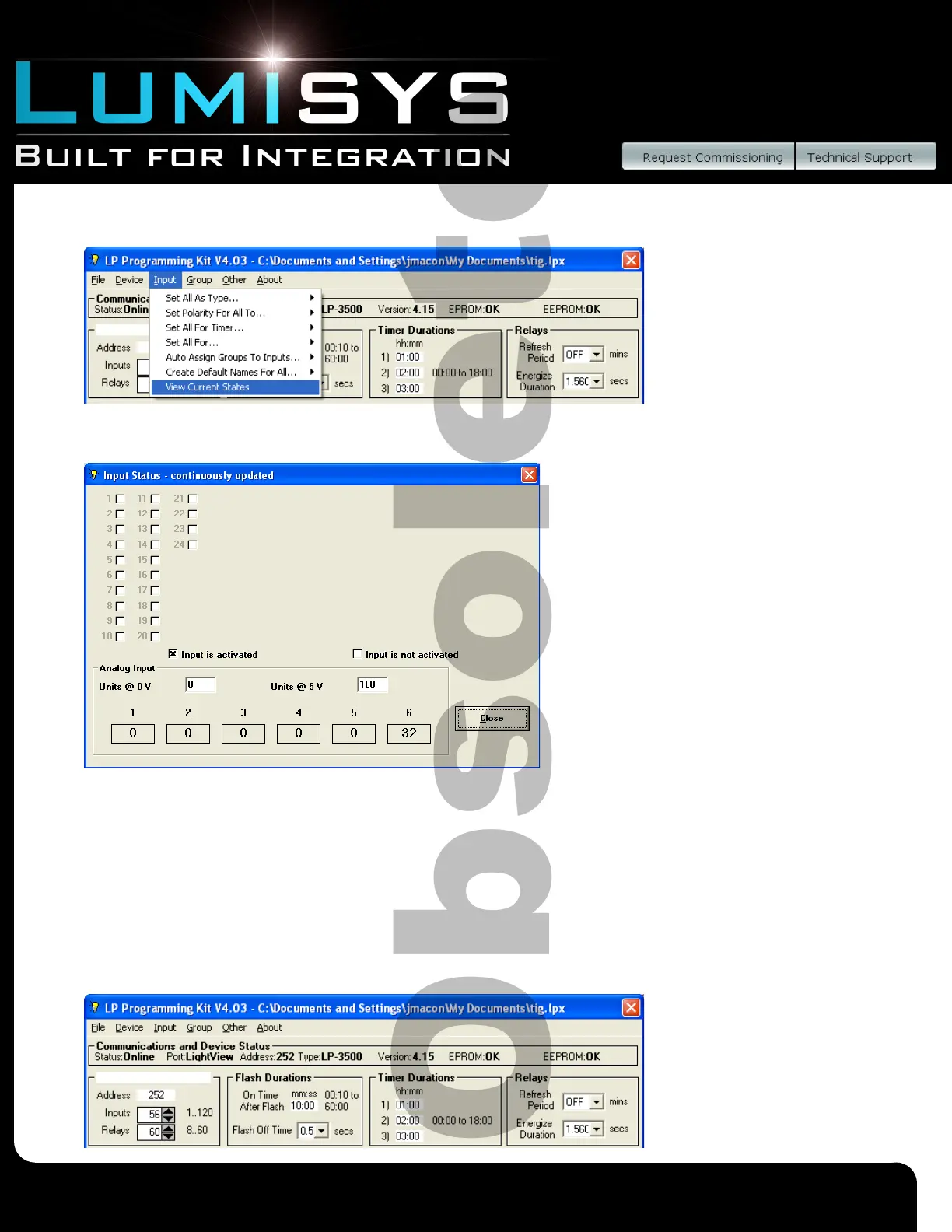
1) From the toolbar select “Input”, then “View Current States”.
2) An Input Status screen will appear to continuously display input status for each input congured in the database. To set the
number of inputs in the LRP Controller database, see the instructions titled “Number of Inputs”.
3) The boxes and numbers represent the input numbers. An “X” in the box indicates the input is activated. Momentary inputs
will only display the “X” for the duration of the momentary closure.
4) The area labeled “Analog Input” allows you to select a value range from 0-255 with which LP-PK will dispay a value in
proportion to 0-5VDC analog input signal. Analog inputs 1-6 are for L28 Controllers with an AI-6 module. All other
controllers use only input 5. If there is no analog input connected the analog input value will display “0”. Input should be
limited to 6 VDC maximum; displayed values should be interpreted accordingly.
Configuring Outputs
Number of Relays/Outputs
1) Select the number of outputs that will be utilized by typing in a number between 1 and 60 in the box labeled “Outputs”.
This number should match the number of outputs to be controlled.
2) To save this information to a le
or to the LRP Controller see
“General LRP Controller Data
- Save File and Write Database to
LRP Controller”.
 Loading...