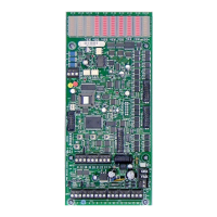
Lighting Relay Panel
Controller User’s Guide
www.lumisys1.com
Due to continuous product improvement, Lumisys reserves the right to change product specications without notice.
Page 12
• To determine the address of the LRP Controller add the value of LEDs 2-9 that are blinking. All LEDs blinking will repre
sent address 255.
• To increment the address by one press the OVER (or CH) pushbutton.
Continue to increment until the desired network
address is displayed.
• To decrement the address by one press the STAT (or TG) pushbutton.
Continue to decrement until the desired network address is displayed.
• To save the network address to non-volatile memory, press the AUTO (or BK) pushbutton.
This will also return the LRP Controller to auto mode.
• Failure to Press the AUTO (or BK) pushbutton will result in loss of network address after power failure because it will
not be saved to non-volatile memory.
Wake-Up LEDs
• After 10 minutes of no pushbutton activity the LEDs will enter an LED saver mode much like a screen saver mode on a PC.
• To wake up the LEDs press the STAT (or TG) pushbutton. The LED’s will illuminate to display group and output status.
Resetting the LRP Controller
• The LRP Controller can be reset if you are experiencing abnormal behavior Resetting is the same as powering down
and powering back up the LRP Controller.
• This will load the data saved in its non-volatile EEPROM into its RAM.
• To reset the LRP Controller press the three pushbuttons OVER (or CH), AUTO (or BK) and STAT (or TG) simultaneously.
Pushbutton Mode Expiration
• Override, Stat and address-set modes (as well as LED illumination) will time-out in 10 minutes with no pushbutton
button activity.
• Mode expiration does not restore relays or save a new address until AUTO (or BK) is pressed. In the meantime how
ever, relays will respond to new serial commands and inputs.
• Each LRP Controller is network ready for RS-485 with 500 volt isolation circuitry.
• Up to 255 LRP Controllers can be networked over a twisted pair of wires.
• LUMISYS LRP Controllers provides seamless integration with the following Building Automation Systems (BAS):
• Alerton Technologies via LUMISYS BACNET or Modbus E-Link
• Andover Controls via programmable port in their controller
• Automated Logic via LUMISYS BACNET E-Link
• BACNET via LUMISYS E-Link
• Delta Controls via LUMISYS BACNET E-Link
• Honeywell via LUMISYS BACNET or Modbus E-Link
• Johnson Controls Metasys via Direct Connect
• MODBUS via LUMISYS Modbus E-Link
• Siemens Building Technologies via Open Processor with LUMISYS driver
• Teletrol Systems via programmable port in their controller
• Trane Company via LUMISYS BACNET E-Link
• Others available, ask your LUMISYS System Provider for details.
• Pressing the STAT (or TG) Pushbutton displays the serial status on the L28 Series. Network Communications status
is always displayed on the non-L28 Series controllers. See the “Group Output and System Status LEDs” section in this
user guide that denes the signicance of each STATUS LED.
LRP Controller Network Features

 Loading...