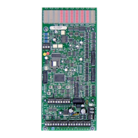
Lighting Relay Panel
Controller User’s Guide
www.lumisys1.com
Due to continuous product improvement, Lumisys reserves the right to change product specications without notice.
Page 9
• Linked On inputs are designed for multi-level lighting control applications that require timers for automatic shutoff of
lighting. A typical application is 1/3, 2/3 and 3/3 lighting levels in conference room. One input is assigned to the 1/3
level output and a second input to the 2/3 level output. Typically two additional inputs are assigned as Momentary Off
inputs for the 1/3 and 2/3 outputs. Activating the 1/3 light level switch will turn on the respective output and begin its
timer. Once the timer has expired the 1/3 light level output will ash to warn the occupants that the lights are about to
turn off. Once the lights ash the two switches, 1/3 and 2/3, are linked as one so either the 1/3 or 2/3 switch can be
activated to reinitialize the timer for the 1/3 lighting level. Immediately after either switch is activated the switches are
automatically un-linked and return to their independent state until another ash warning occurs. Without this features a
user may accidentally activate the wrong level switch causing frustration for the user.
• Change State inputs are designed for use with maintained 3-way switches in retrot applications. A change of state will
toggle the state of the associated output.
Analog Input
• Each LRP Controller with the exception of the L28 Series Controller provides an input for accepting a 0-5 VDC signal
up to a maximum of 6 VDC for LUMISYS’ LS Series Light Sensors Model LS Series /I-5V-0-5 for indoor level,
LS Series /O-5V-0-5 for outdoor light level and LS Series /S-5V-0-5 for skylight levels.
Input Polarity
• Each input can be assigned either normally open or normally closed polarity.
Assigning an Input to control an Output Group
• Any input can control any output.
• Multiple inputs can control the same output.
• Some inputs have higher priority than others see “Input Types” for details.
Output Flash
• Any output can be assigned to ash before turning off to warn the occupants that the lights will be turning off in the next
1-60 minutes. This feature is typically called Flash Warning.
• Outputs can be assigned to turn off with no Flash Warning. Do not select Output Flash for HID lighting that require time
to restrike after turning off.
Maintained Input Priority
• This feature provides the capability to set a hierarchy of exclusive control for maintained inputs that control an output.
• The four priorities are None, Maintained ON, Maintained OFF and Maintained ON/OFF.
• None Priority will provide no priority to the maintained input thus allowing
inputs or network commands to gain control of its associated output.
• Maintained ON Priority will gain control of its assigned output and not allow any other input or network command to
turn its assigned output off.
• Maintained OFF Priority will gain control of its assigned output and not allow any other input or network command to
turn its assigned output on.
• Maintained ON/OFF Priority will gain control of its assigned output and not allow any other input or network command
to turn its assigned output on or off. This is the highest priority.
View Current Input States
• With the use of LP-PK software and laptop or PC, the status of all the LRP Controller inputs can be reviewed at any time.
• Momentary inputs will display their on status only for the duration of the momentary closure.

 Loading...