Lighting Relay Panel
Controller User’s Guide
www.lumisys1.com
Due to continuous product improvement, Lumisys reserves the right to change product specications without notice.
Page 5
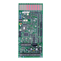
L2732-Kit, Figure 1 is a picture of the LRP Controller used for Models: L2532-K, L2632K, L2930-K, L2732-K, L35 Series,
L26 Series and TRIATEK Legacy Products: L2500 and RCS1000.
Figure 2 is a picture of the LRP Controller used for the L28 Series.
The difference between the two LRP Controllers is the number of inputs and outputs and the type of output device it controls
as listed in Table 1.
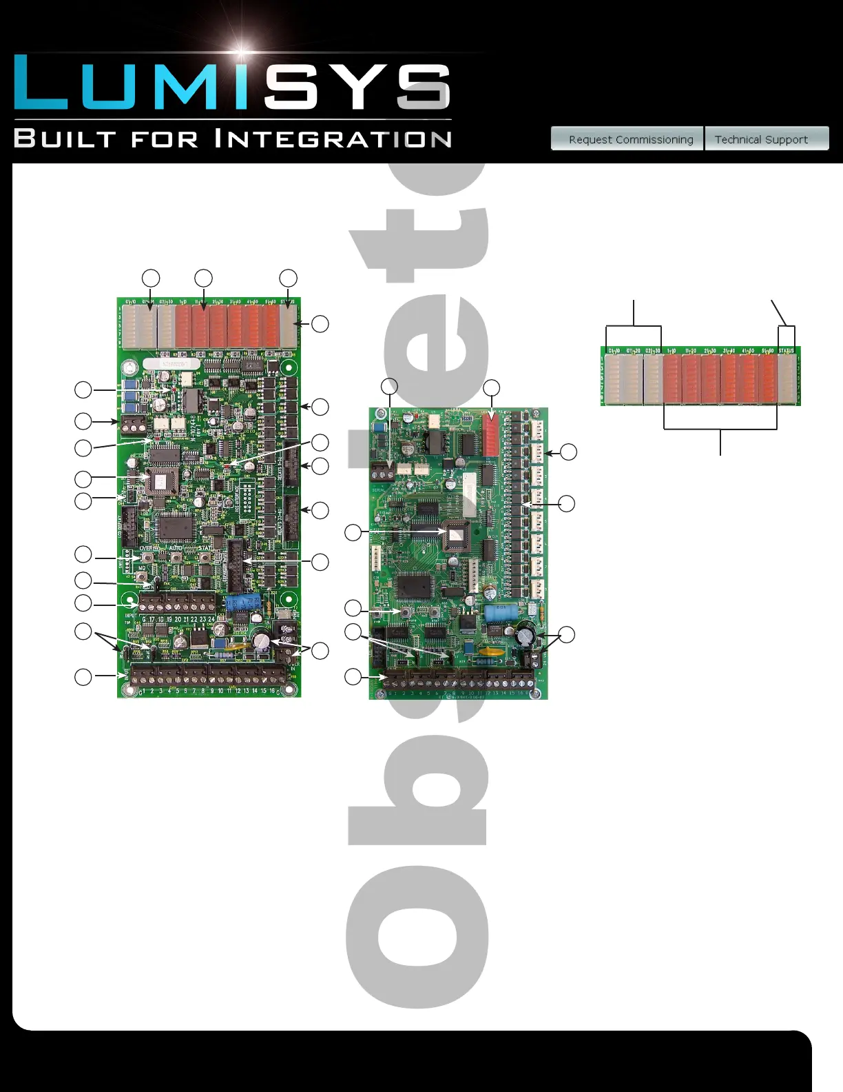
Group, Output and System Status LEDs
1. Group Status LED’s show the status of each of the LRP Controllers 60 lighting groups. The green LEDs labeled G1-G30
indicate output group status. If the associated LED is on then the group is on. If the LED is ashing, then the group is on
but in the Flash Warning mode and will automatically turn off after the On-Time After Flash has expired. In normal
operation, the AUTO (or BK) pushbutton is used to toggle the display between groups 1-30 and groups 31-60. System
Status LED 2 indicates which set of group status is being displayed. If Status LED 2 is off then groups 1-30 status are
being displayed and if Status LED 2 is on then groups 31-60 status are being displayed.
2. Output Status LED’s show the status of each of the LRP Controllers outputs. The L26 Series series and RCS-1000 use
outputs with auxiliary contacts so the associated red LEDs show the state based on the state of the outputs auxiliary
contact. Otherwise the output status LED will show the LRP Controllers commanded state of the output. If the LED is on
the output is on and if the LED is off its associated output is off.
LRP Controller Hardware Features
Figure 1 Figure 2
1. Group Status
2. Output Status
3. System Status
See Figure 1
A description of each numbered
item is listed below.
5
17
9
11
13
14
16
15
18
1 2 3
6
17
7
12
15
18
9
9
11
11
4
16
10
13
13
8
14
 Loading...