Document Name:
LX Eos user’s manual
INPUT (RJ11 – 6pin connector)
CAN port (RJ45 – 8pin connector)
SD port (RJ11 – 6pin connector)
Use only LX SD card adapter.
GPS antenna
Connect external GPS antenna to this connector. LX Eos must have external antenna connected all the
time, else internal flight recorder will now work.
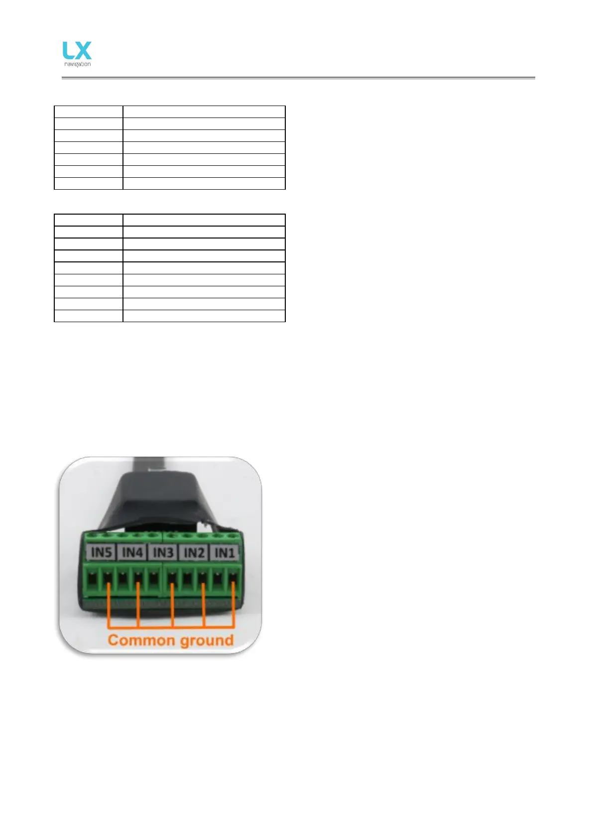
18.4 External switch installation
Up to five external switches can be connected to LX Eos.
To connect external switch to LX Eos you have to use
external switch interface board (included in package).
Every slot available has a signal input and ground input.
The configuration of inputs can be set under Setup ->
Inputs.
User can use two different connection styles:
- 2 wire connection: Connect switch signal and ground
wires to interface board.
- 1 wire connection: Connect switch ground wire to glider
common ground and connect switch signal wire to
interface.
Be careful not to connect signal wire to common ground
input (see picture which are common ground inputs)
Interfaces common ground is connected to glider common
ground via power supply cable (GND).
All inputs except SC will be “active” when switch is closed (signal and ground are in short circuit). If “Inv”
(Invert) is checked on input setting then “active” means when switch is open.
Example: airbrake warning will be active when switch is not closed and Eos is in flight mode. Warning will
disappear when switch will be closed.
SC input has its own setting under Vario/SC menu and can be set to be active on “on”, “off” and “toggle”
state.