Page 51
The Monitor Out and Phones channel strips have an additional button, just like in the Hilo’s Routing page (see section 5.3.4: Routing).
For these two outputs you can control both the digital output level and the analog output level. Clicking the button beneath the fader
will toggle between Analog and Digital level controls.
Analog Output Level – This is your primary monitoring level control. Analog Monitoring is generally preferred for critical listening,
as it has no effect on the depth resolution on the material being attenuated. Thus, analog is the default selection here.
Digital Output Level – For most critical listening contexts, the digital volumes are best left in their default position, with zero
attenuation. However, since Hilo offers you the option of routing several inputs to these outputs, it is possible to overload the digital
output and cause distortion. When this is the case, use the Digital Output control to lower the level feeding the D/A converter. Once
the digital overload has been lessened, you can set the listening volume with the Analog level control.
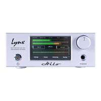
To explore the controls available on the Monitor page, it makes sense to start with the outputs section, the row on the bottom.
Each channel has the following elements in common:
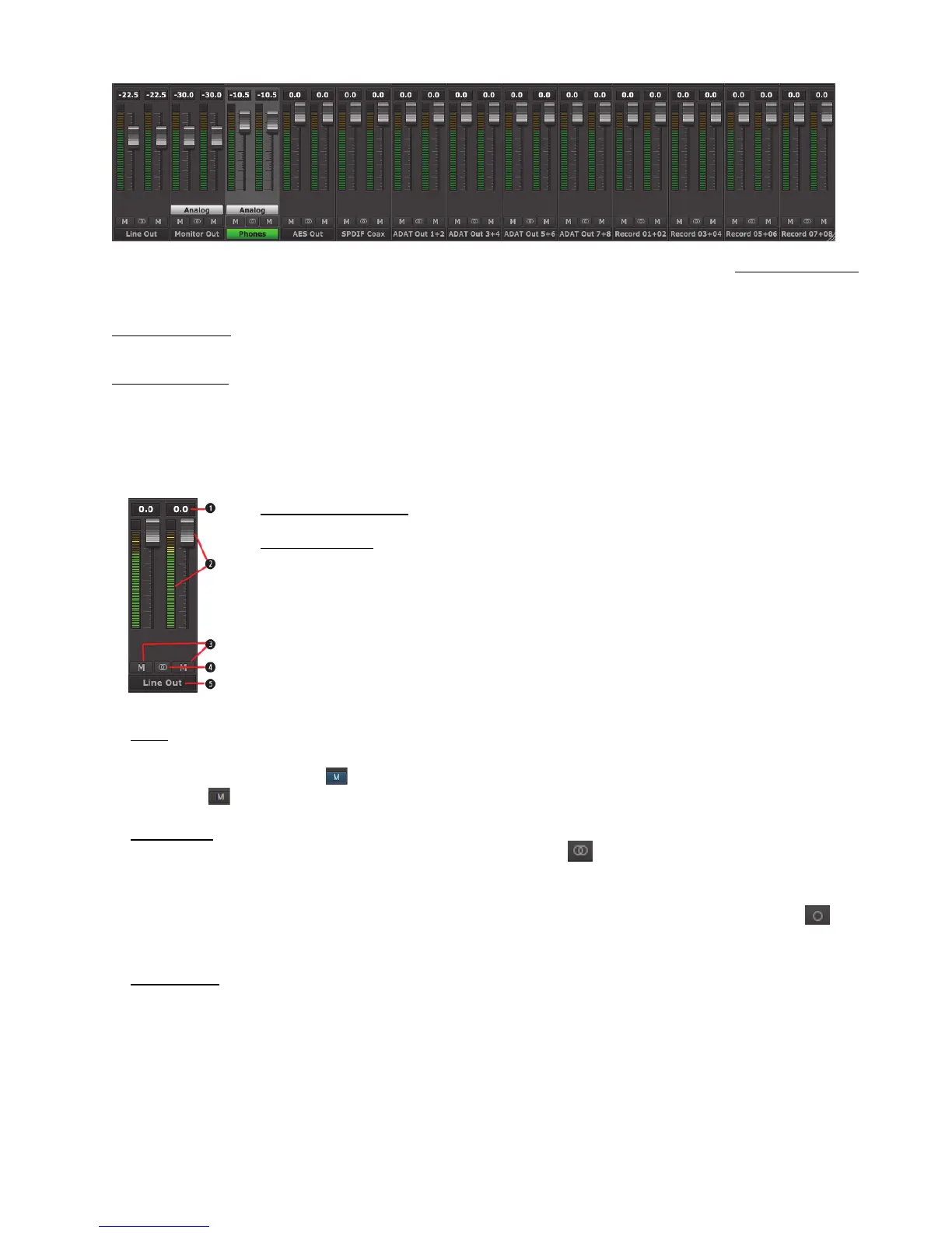
Numeric Level Indicator
This Level Indicator displays the amount of attenuation, in dB, performed on the associated Output.
Faders and Meters
The FADERS in the Outputs row are for attenuation of the output levels. Levels can be reduced in ½ dB
increments with a click-drag of the mouse.
This is the rough equivalent to turning down the faders on a mixing board. If there are several sources
assigned to that output, play and record sources, all will be attenuated when the faders are brought down.
All faders, except Monitor Out and Phones when in “analog” mode, can be attenuated at the same time by
holding down the CTRL key on the keyboard while click-sliding any single fader.
The METERS in the Outputs section show the level strength of the signals at the associated output. The
Meters are post-fader, so there will be reduction in Meter level as the signal is attenuated.
Mutes
The “M” Icon below the fader is for the Mutes. This switch Mutes or UnMutes the associated output.
When the “M” button is blue like this , then the Mute is ON, and no signal will pass to the selected output. When the “M” button
is gray, like this
, then the Mute button is OFF, and signal CAN pass to the selected output.
Channel Link
In between the two Mute buttons for a pair of Inputs, is the channel link control: . This control toggles the linked state for a pair
of faders and mutes. If two channels ARE linked, then moving the fader for one of them will move both channels. Similarly, if one is
muted then both will mute. If the faders between the channels are offset, when one is moved the other will snap to the same position.
Linked is the default state for pairs of inputs. To “un-link” a pair, click on the link icon and it will change to a single circle: . In
this state, the mute, fader and pan controls operate on a single channel independently.
Output Button
This identifies the outputs that are applicable to the fader and mute controls, and is also used to facilitate routing. Hilo Remote uses an
output oriented approach to routing. Clicking on an output button, “selects” that output for sources to be assigned to it. When selected,
the output label button is green. In this state, sources from the Record or Play sections can be un-muted, thereby set to stream to the
“selected” output.
In the mixer’s default state, each output has one or more LSLOT play devices routed to it. All physical outputs (record streams
excepted) have Play 1+2 assigned to it. When you click through to select different outputs, Play 1+2 will show as un-muted for all of
them. In addition, some outputs have Play 1+2 as well as other Play pairs.