Page 53
Mutes
The “M” Icon below the fader is for the Mutes. This switch Mutes or UnMutes the input signal routed to an output. As
with the faders, this control is specific to the patch point between the input source, and the selected output. It does not control whether
the input signal itself is muted, or whether that input signal can be recorded.
When the “M” button is blue like this , then the Mute is ON, and no signal will pass to the selected output. When the “M” button
is gray, like this , then the Mute button is OFF, and signal WILL pass to the selected output.
Inputs are muted by default. When an output is selected from the outputs pane, inputs need to be un-muted to become active. When an
input source is no longer being monitored, then it is good practice to mute it again so that unintended mic bleed or system noise is not
corrupting the signal path.
Channel Link
In between the two Mute buttons for a pair of Inputs, is the channel link control: . This control toggles the linked state for a pair
of faders and mutes. If two channels ARE linked, then moving the fader for one of them will move both channels. Similarly, if one is
muted then both will mute. If the faders between the channels are offset, when one is moved the other will snap to the same position.
The linked state also impacts the Pan controls. If one pan pot is moved to the left the other will move a corresponding amount to the
right. For instance, if the left pot is set to -25, the right channel will pan to +25.
Linked is the default state for pairs of inputs. To “un-link” a pair, click on the link icon and it will change to a single circle:
. In
this state, the mute, fader and pan controls operate on a single channel independently.
Input Label
This identifies the Input that is applicable to the fader, pan, mute and input select controls.
The MONITOR page can be used to create complex headphone mixes for an artist, allow mirroring of play streams to multiple
outputs, even send completely different source material to different speaker pairs. Here are some visual examples of routing
configurations that are possible:
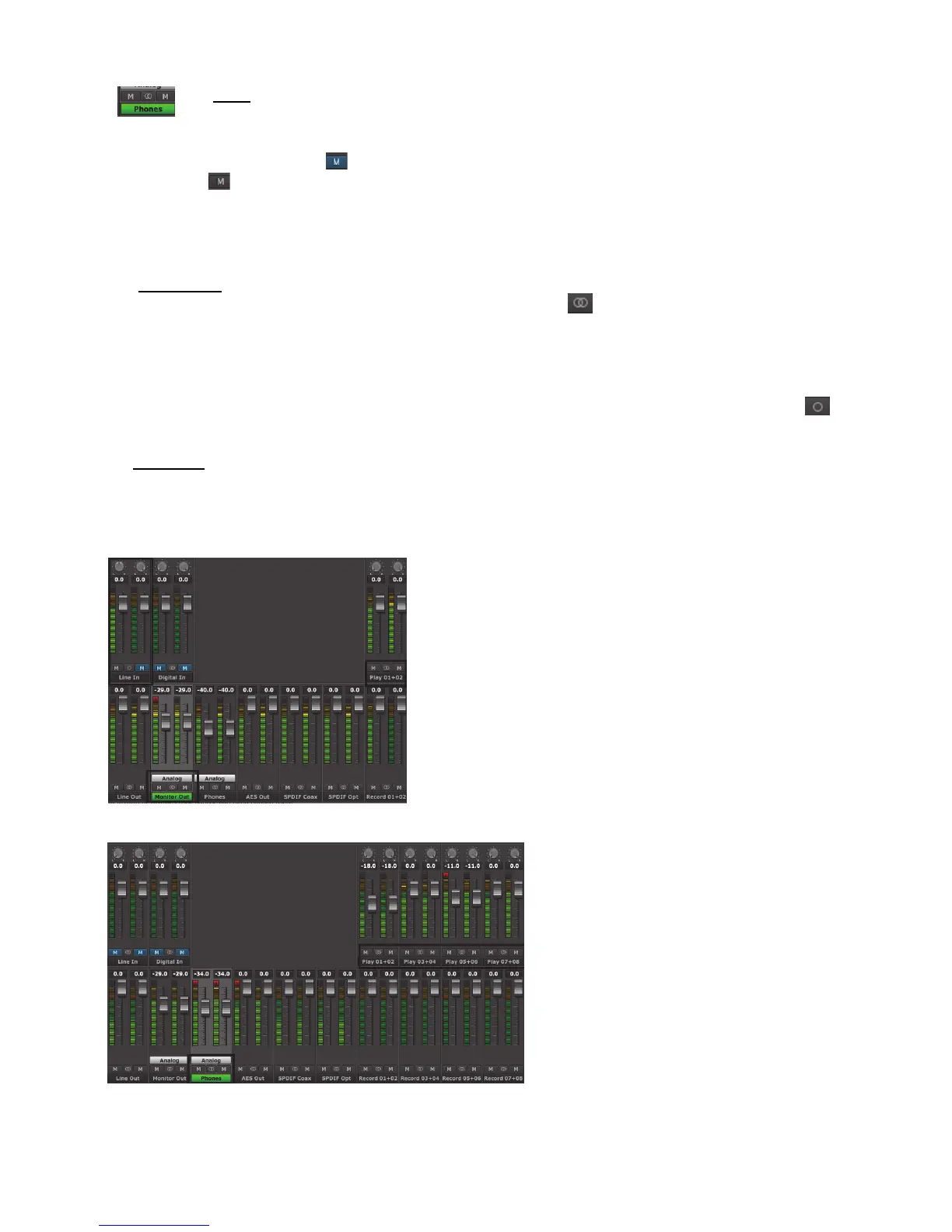
In this example, the selected output is MONITOR OUT. We are sending
signal from Play 1+2, existing tracks from a multi-track session.
In addition we are sending signal from the LINE INPUT left channel. The
Line Inputs were “un-linked”, and only the left channel is un-muted, so signal
is passing only from the left channel. Note, that the pan position for LINE IN
left is in the center, so the source will be heard equally through both channels
of the MONITOR OUT.
The Play 1+2 streams are at zero attenuation, as is the Line In. Monitor Out is
attenuated by 29dB.
This would be a common configuration for overdubbing into a project.
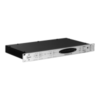
In this example, four stereo stems are sent from the
DAW to the PHONES out.
The PHONES level is attenuated by 34dB. The stems
also have varying levels, Play 1+2 is attenuated by 18dB,
Play 5+6 by 11dB, whereas Play 3+4 and 7+8 are at
unity
Here, all of the channels are linked as stereo pairs. Keep
in mind, the settings in the Input row are relative to the
Output selected. If Line Out is selected, the mute states,
fader positions and channel link status of the input
devices would be completely different.