214633 17 Revision C
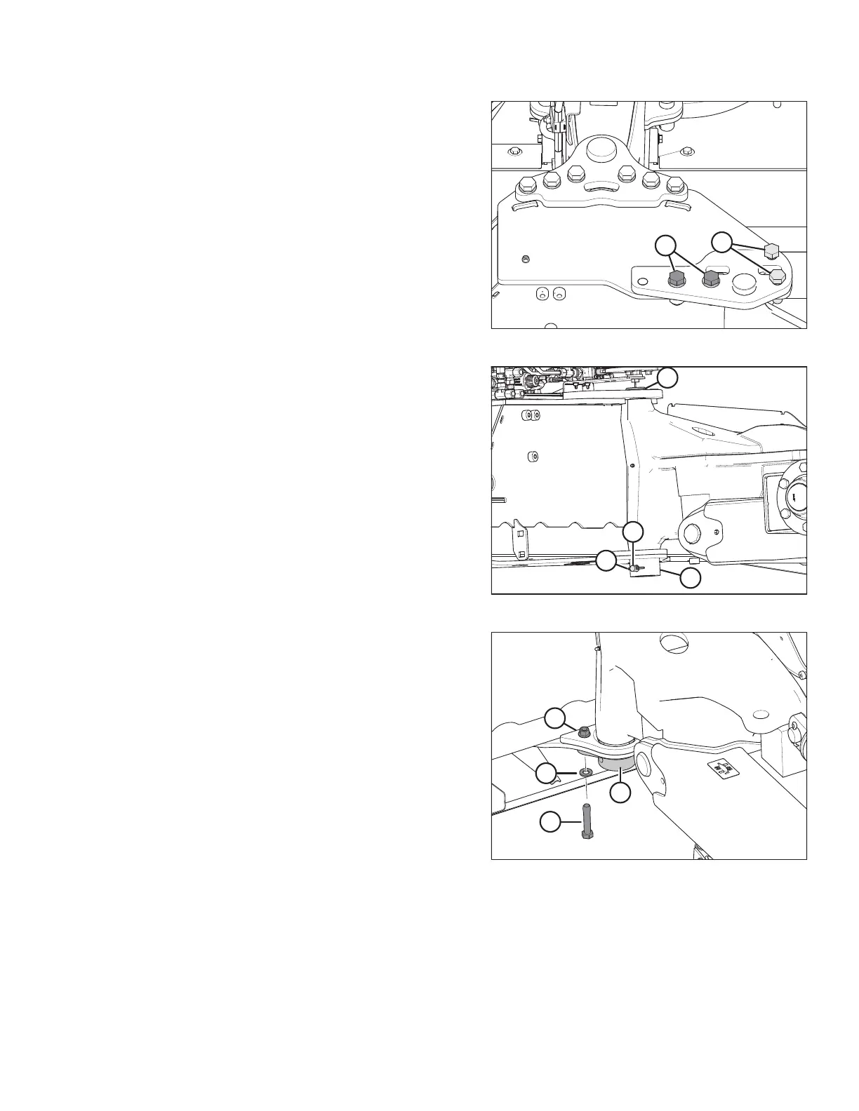
Figure 3.11: Pin Support
6. Install two M20 x 65 bolts (A) (MD #136157), hardened
washers (MD #112130), and nuts (MD #136122).
7. Temporarily install bolts (B) to help align the assembly.
Figure 3.12: Pin Installation
8. Rotate pin (A) until hole in pin aligns with holes in welded
collar (B). Insert pin (C) (MD #19958) through the collar
and pin.
9. Insert cotter pin (D) (MD #18608) and bend over the legs to
secure it.
Figure 3.13: Pin Support
10. For model year 2018 and prior:
NOTE:
Retrieve the parts in this step from the transport pin kit
(MD #259258) (must be ordered separately).
Attach pin support (A) (MD #259105) to the bottom of the
carrier frame, beneath the transport pin, with two M12 hex
head bolts (B) (MD #237316), two M12 flat washers (C)
(MD #184714), and two M12 hex flange lock nuts (D)
(MD #136431). Drill holes if necessary. Reinstall clevis and
cotter pin to secure hitch pin.
NOTE:
Only one set of hardware shown in the illustration. The
other set is hidden behind the transport tube.
INSTALLATION INSTRUCTIONS