214633 37 Revision C
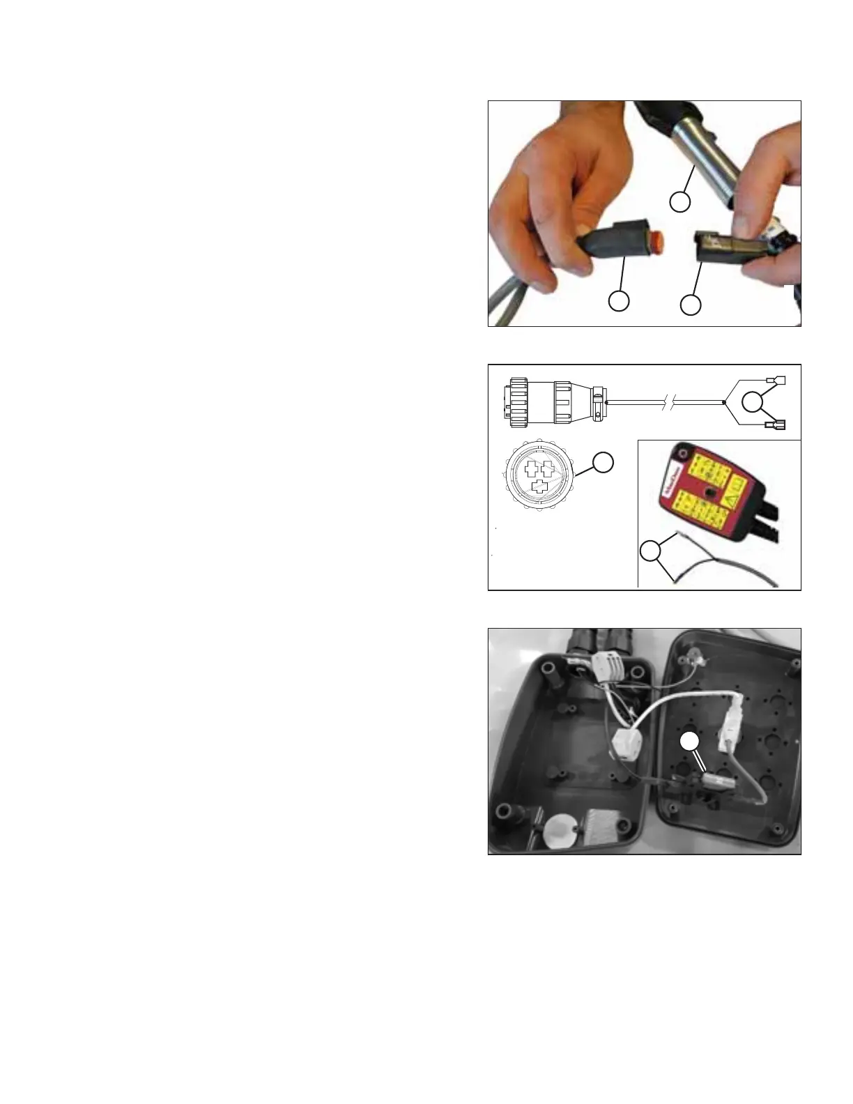
Figure 3.62: Transport Harness
3. Locate connector (C) that branches off seven-pole transport
plug (A) and attach it to remote wiring harness (B).
Figure 3.63: Three-Pin Auxiliary Connector
4. If your tractor has a three-pin auxiliary power connection:
NOTE:
The remote control has internal protection which prevents
damage caused by incorrect wiring, short circuits, or
overload conditions.
Connect two wires (B) from three-pin auxiliary
connector (A) (MD #281615) to remote control wires (C) on
the remote control, wrap connections with electrical tape,
and proceed to Step 6, page 38.
• The wire with no tag connects to the tractor ground.
• The wire with the red tag connects to the tractor power.
Figure 3.64: Control Box Interior
NOTE:
If connections are reversed, the lamp will not illuminate
when the toggle switch is in field mode. Try the following to
correct the issue:
• Check if 10 amp fuse (A) located inside the transport
control box has blown.
• Check for short in wires to solenoid valve on header.
• Check for incorrect wire connections (reversed) at the
power supply or solenoid valve.
INSTALLATION INSTRUCTIONS