r-net user guide
11 5940A R-net User Guide DCR1266
magicmobility.com.au
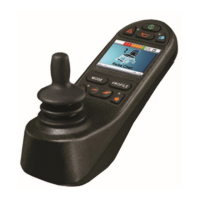
4.2.7 HAZARD WARNING BUTTON AND LED
This button activates and de-activates the wheelchair’s hazard lights. Depress the button to turn the hazards
on and depress the button again to turn them off. When activated the hazard LED and the indicator LEDs will
flash in sync with the wheelchair’s indicators.
4.2.8 LIGHTS BUTTON AND LED
This button activates and de-activates the wheelchair’s lights. Depress the button to turn the lights on and
depress the button again to turn them off. When activated the lights LED will illuminate.
4.2.9 LEFT INDICATOR BUTTON AND LED
This button activates and de-activates the wheelchair’s left indicator. Depress the button to turn the indicator
on and depress the button again to turn it off. When activated the left indicator LED will flash in sync with the
wheelchair’s indicator(s).
4.2.10 RIGHT INDICATOR BUTTON AND LED
This button activates and de-activates the wheelchair’s right indicator. Depress the button to turn the
indicator on and depress the button again to turn it off. When activated the right indicator LED will flash in
sync with the wheelchair’s indicator(s).
4.2.11 EXTERNAL ON/OFF SWITCH JACK
This allows the user to turn the control system on and off using an external device, such as a buddy button.
4.2.12 EXTERNAL PROFILE SWITCH JACK
This allows the user to select Profiles using an external device, such as a buddy button. To change the Profile
whilst driving simply press the button.
If the control system is set to latched drive or actuator control operation, then the polarity of the jack input is
reversed to effect a fail-safe system; meaning this input will provide an External Profile Switch function and an
Emergency Stop Switch function.
NOTE:
The Joystick Module is supplied with rubber bungs that must be inserted into the Jack Socket when no
external device is connected.