EasyManuals Logo

Magic Mobility R-NET CJSM2 User Manual

Magic Mobility R-NET CJSM2
45 pages
To Next Page IconTo Next Page
To Previous Page IconTo Previous Page
Page #15 background imageLoading...
Page #15 background image
r-net user guide
15 5940A R-net User Guide DCR1266
magicmobility.com.au
5.3.1 IDENTIFIED MODULE
This identifies which module of the control system has registered the problem, such as:
PM Power Module
JSM Joystick Module
ISM Intelligent Seating/lighting Module
5.3.2 TRIP TEXT
The Trip Text gives a brief description of the trip type.
5.3.3 TRIP CODE
The 4-digit code displayed gives the exact trip that has been recorded.
5.3.4 DIAGNOSTIC PROCEDURE
Please follow this procedure:
Read and note the Trip Text displayed, the identified Module and the Trip Code.
Switch off the control system.
Make sure that all connectors on the listed Module and the wheelchair are mated securely.
Check the condition of the battery.
Note the Trip Text description, and take the required action.
Switch on the control system again and try to drive the wheelchair. If the safety circuits operate again,
switch off and do not try to use the wheelchair. Contact your service agent.
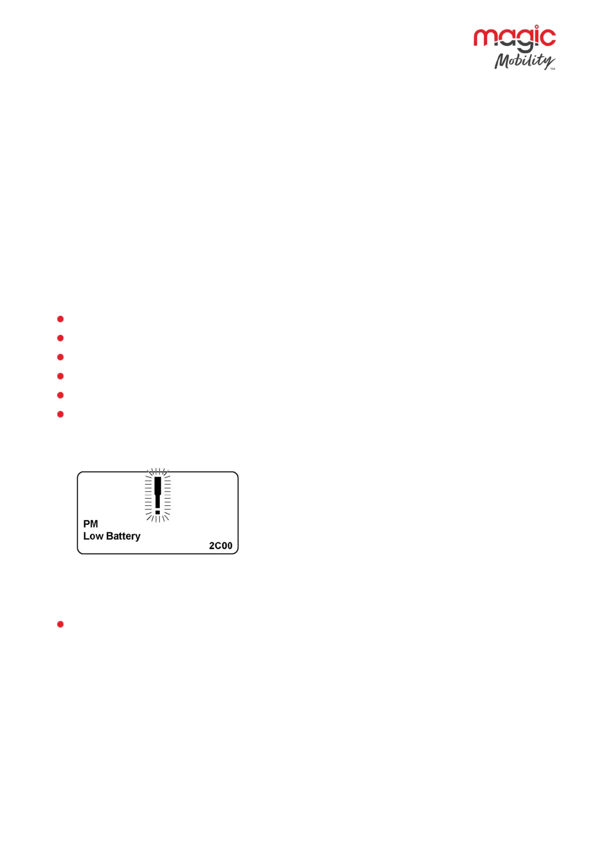
Example:
Identified Module Power Module
Trip Text Low Battery
Trip Code 2C00
This means the battery needs charging or there is a bad connection to the battery.
Check the connections to the battery. If the connections are good, try charging the battery.
5.4 Locking the control system
The Control System can be locked in one of two ways. Either using a button sequence on the keypad or with a
physical Key. How the Control System is locked depends on how the wheelchair manufacturer has
programmed the system.

Table of Contents

Questions and Answers:

Question and Answer IconNeed help?

Do you have a question about the Magic Mobility R-NET CJSM2 and is the answer not in the manual?

Magic Mobility R-NET CJSM2 Specifications

R-Net 80

Power IconPower
supply voltage24 Vdc
operating voltage16 Vdc to 35 Vdc
peak voltage35 Vdc
Current IconCurrent
brake current200 µA min. 1 A max.
battery charging current12 Arms max.
maximum drive current80 A
Environmental Specifications IconEnvironmental Specifications
moisture resistanceIPX4
operating temperature-25°C to +50°C
storage temperature-40°C to +65°C

R-Net 90

Power IconPower
supply voltage24 Vdc
operating voltage16 Vdc to 35 Vdc
peak voltage35 Vdc
Current IconCurrent
brake current200 µA min. 1 A max.
battery charging current12 Arms max.
maximum drive current90 A
Environmental Specifications IconEnvironmental Specifications
moisture resistanceIPX4
operating temperature-25°C to +50°C
storage temperature-40°C to +65°C

R-Net 120

Power IconPower
supply voltage24 Vdc
operating voltage16 Vdc to 35 Vdc
peak voltage35 Vdc
Current IconCurrent
brake current200 µA min. 1 A max.
battery charging current12 Arms max.
maximum drive current120 A
Environmental Specifications IconEnvironmental Specifications
moisture resistanceIPX4
operating temperature-25°C to +50°C
storage temperature-40°C to +65°C

Related product manuals