EasyManuals Logo

Magic Mobility R-NET CJSM2 User Manual

Magic Mobility R-NET CJSM2
45 pages
To Next Page IconTo Next Page
To Previous Page IconTo Previous Page
Page #14 background imageLoading...
Page #14 background image
r-net user guide
14 5940A R-net User Guide DCR1266
magicmobility.com.au
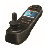
5.1.10 CONTROL SYSTEM TEMPERATURE
This symbol is displayed when the control system has intentionally reduced its
own power, in order to protect itself against heat damage.
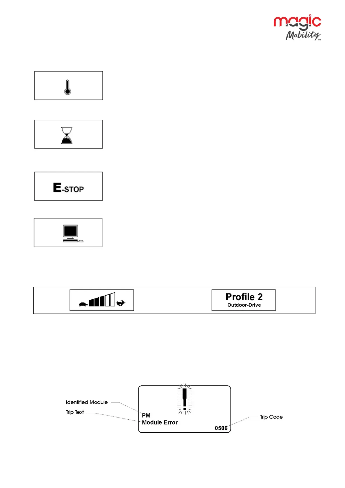
5.1.11 TIMER
This symbol is displayed when the control system is changing between different
states. An example would be entering into Programming Mode. The symbol is
animated to show the sands falling.
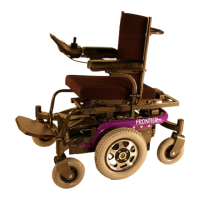
5.1.12 E-STOP
If the control system is programmed for latched drive or actuator operation, then
it is normal for an Emergency Stop Switch to be connected into the External
Profile Switch Jack. If the Emergency Stop Switch is operated or disconnected,
this symbol will be displayed.
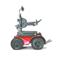
5.1.13 BLUETOOTH
When Bluetooth Mode is entered the screen will display the following icon.
5.2 Momentary screens
If the momentary screens are programmed to be displayed, then pressing the Speed or Profile Buttons will
display screens such as below.
Speed Momentary Screen Profile Momentary Screen
5.3 Diagnostic screen
When the control system safety circuits have operated, and the control system has been prevented from
moving the wheelchair a diagnostics screen will be displayed.
This indicates a system trip, i.e. the R-net has detected a problem somewhere in the wheelchair’s electrical
system.
If the error is in a non-active module, for example in the ISM but with a drive Profile is selected, then drive will
still be possible, however, the diagnostic screen will appear intermittently.

Table of Contents

Questions and Answers:

Question and Answer IconNeed help?

Do you have a question about the Magic Mobility R-NET CJSM2 and is the answer not in the manual?

Magic Mobility R-NET CJSM2 Specifications

R-Net 80

Power IconPower
supply voltage24 Vdc
operating voltage16 Vdc to 35 Vdc
peak voltage35 Vdc
Current IconCurrent
brake current200 µA min. 1 A max.
battery charging current12 Arms max.
maximum drive current80 A
Environmental Specifications IconEnvironmental Specifications
moisture resistanceIPX4
operating temperature-25°C to +50°C
storage temperature-40°C to +65°C

R-Net 90

Power IconPower
supply voltage24 Vdc
operating voltage16 Vdc to 35 Vdc
peak voltage35 Vdc
Current IconCurrent
brake current200 µA min. 1 A max.
battery charging current12 Arms max.
maximum drive current90 A
Environmental Specifications IconEnvironmental Specifications
moisture resistanceIPX4
operating temperature-25°C to +50°C
storage temperature-40°C to +65°C

R-Net 120

Power IconPower
supply voltage24 Vdc
operating voltage16 Vdc to 35 Vdc
peak voltage35 Vdc
Current IconCurrent
brake current200 µA min. 1 A max.
battery charging current12 Arms max.
maximum drive current120 A
Environmental Specifications IconEnvironmental Specifications
moisture resistanceIPX4
operating temperature-25°C to +50°C
storage temperature-40°C to +65°C

Related product manuals