16
57-642 ECLIPSE Model 705 Guided Wave Radar Transmitter for Hygienic Industries
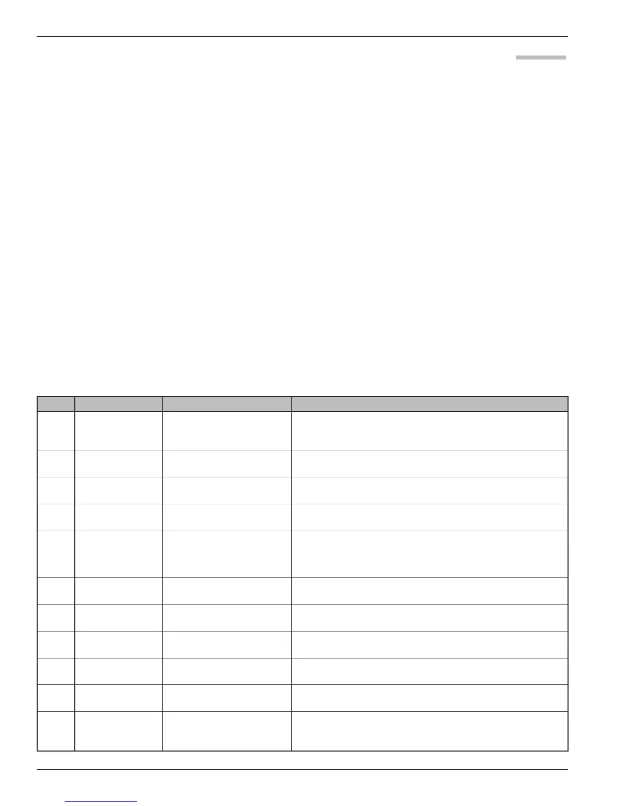
2.6.5 Model 705 Menu: Step-By-Step Procedure
The following tables provide a complete explanation of
the software menus displayed by the ECLIPSE transmitter.
Use these tables as a step-by-step guide to configure the
transmitter based on a desired measurement type of:
• Level Only, Section 2.6.5.1
• Level and Volume, Section 2.6.5.2
The tables are separated to display the parameters based
on the measurement type. The second column presents
the menus shown on the transmitter display. The displays
are in the order they would appear if the arrow keys were
used to scroll through the menu. The numbers in the first
column are not shown on the display. They are only pro-
vided as a reference.
The third column provides the actions to take when con-
figuring the transmitter. Additional information or an
explanation of an action is given in the fourth column.
(Shaded sections are factory menu items.)
2.6.5.1 Measurement Type: Level Only (Loop Control = Level)
Display Action Comment
1
*Status*
*Level *
*% Out *
* Loop *
Transmitter Display LoopCtrl = Level.
Transmitter default display showing Status, Level, % Output, and
Loop values cycles every 5 seconds
2
Level
xxx.x
Transmitter Display Transmitter displays Level Value in selected units
3
% Output
xx.x%
Transmitter Display Transmitter displays % Output measurement derived from 20 mA
span
4
Loop
xx.xx mA
Transmitter Display Transmitter displays Loop value (mA)
5
PrbModel
(select)
Select the type of probe
used
(Example: 7xR-x)
Select from 7xF-E or 7xH-X as shown on the probe nameplate
6
PrbMount
(select)
Select the type of probe
mounting
Select Flange
7
MeasType
(select)
Select type of measurement Select Lvl Only
8
LvlUnits
(select)
Select level units Select from cm, inches, feet or meters
9
Probe Ln
xxx.x
Enter the exact length of
probe
Note that the original probe may have been shortened by the
skid or vessel manufacturer to fit the vessel.
10
Lvl Ofst
xxx.x
Enter the desired reading
when probe is dry
Level Offset is the distance from the probe tip to the desired 0
level point (-90 to 300"). Refer to Section 2.6.6
11
Dielctrc
(select)
Select range bounding the
dielectric constant of the
media
Select 10–100