41
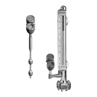
57-642 ECLIPSE Model 705 Guided Wave Radar Transmitter for Hygienic Industries
7.0 Specifications
7.1 Functional
System Design
Measurement Principle Guided time-of-flight via time domain reflectometry
Input
Measured Variable Level, determined by the time-of-flight of a guided radar pulse from
transmitter to product surface and back
Span 6 inches to 24 feet (15 to 732 cm)
Output
Type Analog 4 to 20 mA with HART digital signal (HART 6)
Range Analog 3.8 to 20.5 mA useable
Digital 0 to 999" (0 to 999 cm)
Resolution Analog 0.01 mA
Digital 0.1"
Loop Resistance (maximum) GP/IS/XP- 620 Ω @24 VDC
Diagnostic Alarm Adjustable 3.6 mA, 22 mA, HOLD
Damping Adjustable 0-10 seconds
User Interface
Keypad 3-button menu-driven data entry & system security
Indication 2-line × 8-character display
Digital Communication HART Version 6.x compatible
FO
UNDATION
fieldbus H1 (ITK 4.6)
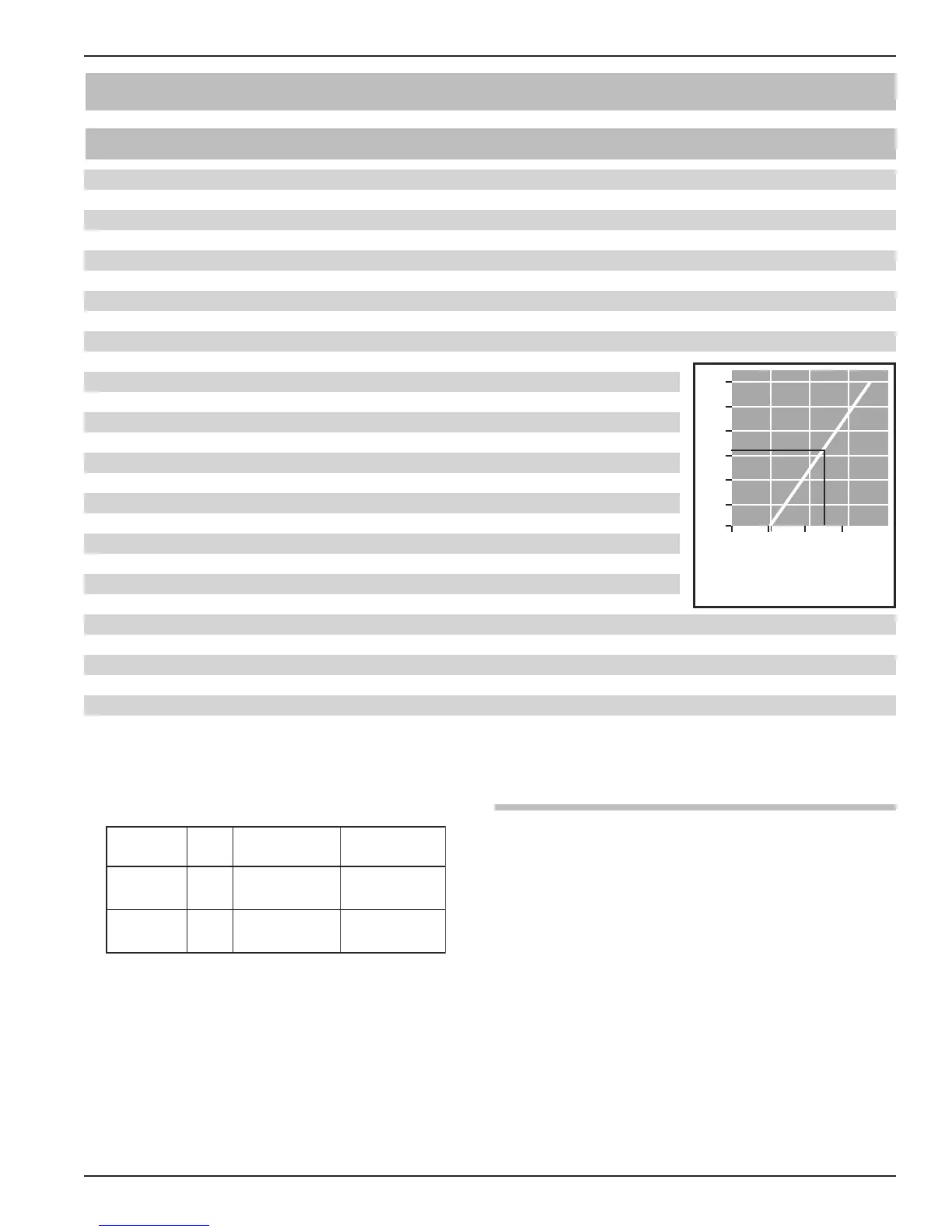
Power (Measured at instrument terminals)
General Purpose/Intrinsically Safe/Explosion Proof/FM/CSA/ATEX 11 to 36 VDC
Fieldbus General Purpose/XP/IS/FISCO 9–32 VDC (17 mA current draw) (Refer to instruction manual 57-640
for additional information on FOUNDATION fieldbus version)
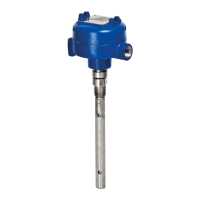
Housing
Material Deep drawn 304 ss single compartment, optional Aluminum A356T6 (<0.20% copper)
or 316L dual compartment
Cable Entry
3
⁄4" NPT and M20: for dual compartment housing
1
⁄2” NPT and M20: for single compartment 304ss housing
1200
1000
800
600
400
200
0
0 10 20 30 40
V
DC
GENERAL PURPOSE (GP)
INTRINSICALLY SAFE (IS)
EXPLOSION PROOF (XP)
20.5 mA
24 VDC
630
11
Ω
➀ Maximum temperature of O-ring (not necessarily maximum process temperature)
Material Code
Maximum
Temperature➀
Min.
Temp.
Viton
®
GFLT 0
+400 °F
(+200 °C)
-40 °F
(-40 °C)
EPDM 1
+250 °F
(+125 °C)
-60 °F
(-50 °C)
7.1.1 O-ring (Seal) Selection Chart – Model 7xH