7
57-642 ECLIPSE Model 705 Guided Wave Radar Transmitter for Hygienic Industries
1.4 QuickStart Configuration
The ECLIPSE transmitter is configured with default
values from the factory but can be reconfigured in the shop
(disregard any fault messages due to unattached probe). The
minimum configuration instructions required in the field
follow. Use the information from the operating parameters
table in Section 1.1.2 before beginning configuration.
1. Power-up the transmitter.
The display changes every five seconds to show one of four
values: Status, Level, %Output, and Loop current.
2. Remove the transmitter cover (the lower electronic compart-
ment of the dual compartment aluminum version).
3. Use the Up or Down Arrow ( ) keys to move from one
step of the configuration program to the next step.
4. Press the Enter Arrow ( ) key. The last character in the
first line of the display changes to an exclamation point (!).
5. Use the Up or Down Arrow ( ) keys to increase or
decrease the value in the display or to scroll through the
choices.
6. Press the Enter Arrow ( ) key to accept a value and move
to the next step of the configuration program (the default
password is 0).
7. After entering the last value, allow 10 seconds before
removing power from the transmitter.
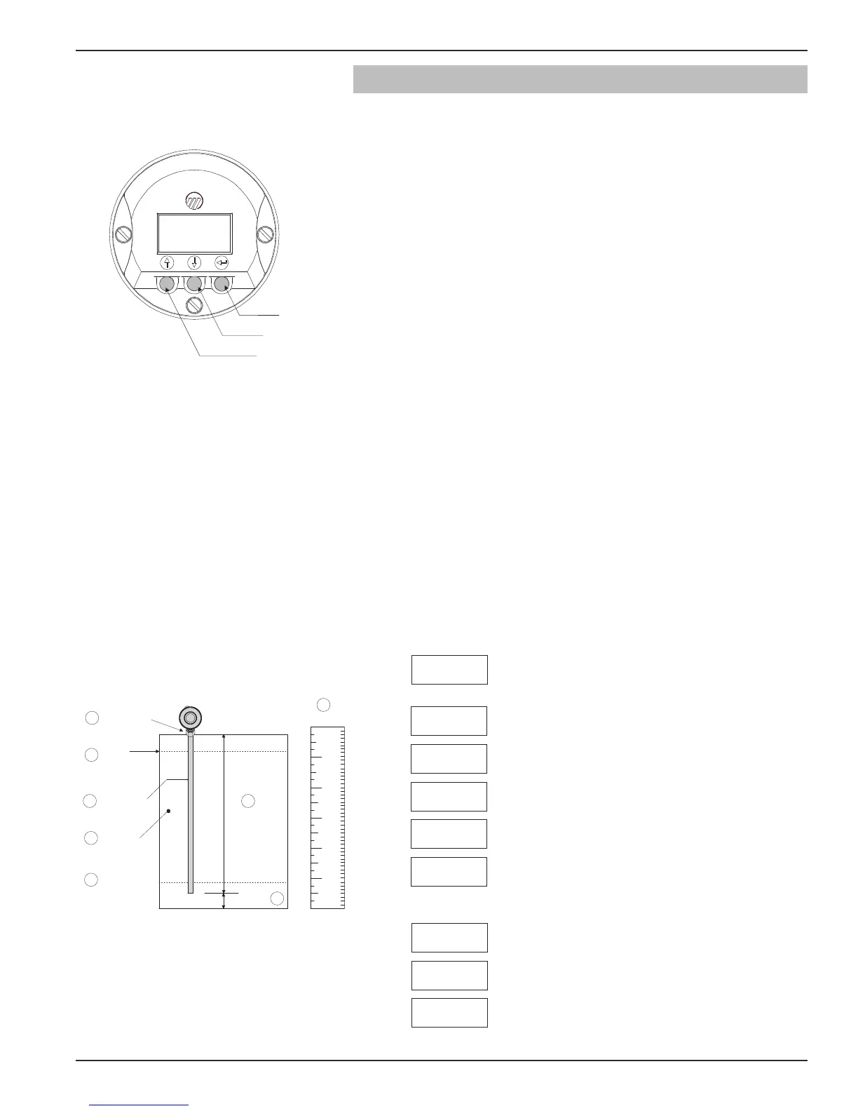
The following configuration entries are the minimum required for
configuration (the default password is 0 from the LCD/keypad).
Lvl Units
xxx
PrbModel
(select)
Probe Ln
xxx.x
LvlOfst
xxx.x
Dielctrc
(select)
Set 4mA
xxx.x
Set 20mA
xxx.x
Select the Probe Model to be used
Model 705: 7xF-E or 7xH-X
Select the type of Probe Mounting to vessel (Flange)
Select from Level Only, Level and Volume, Interface Level
or Interface Level and Volume.
Select the Units of measurement for the level readout (inches,
cm, feet or meters). Not included on Model 705 Fieldbus.
Enter the exact Probe Length.
Enter the Level Offset value. Refer to Section 2.6.6 for
further information. (The unit is shipped from the factory
with offset = 0; i.e., all measurements are referenced to
the bottom of the probe).
Enter the Dielectric range for the material to be measured.
(Typically 10–100 for hygienic applications)
Enter the level value (0%-point) for the 4 mA point (not
included on Model 705 fieldbus).
Enter the level value (100%-point) for the 20 mA point (not
included on Model 705 fieldbus).
Level Offset
Probe Length
Probe Mount
4 mA Level
(0%-point)
Probe Model
Dielectric
of Medium
In or Cm
20 mA
(100% Point)
8
2
6
7
5
4
1
9
NOTE: A small transition zone [0–6" (0–15cm)]
may exist at the top and bottom of the
probe. See Specifications, Section 7.4.
①
②
Æ
Ø
∞
±
≤
⑧
⑨
PrbMount
(select)
MeasType
(select)
➪
➪
➪
➪
➪
➪