14
57-642 ECLIPSE Model 705 Guided Wave Radar Transmitter for Hygienic Industries
2.6 Configuring the Transmitter
The ECLIPSE transmitter is factory-configured but can be
reconfigured easily in the shop (disregard error message
due to unattached probe). Bench configuration provides a
convenient and efficient way to set up the transmitter
before going to the tank site to complete the installation.
Before configuring the transmitter, collect the operating
parameters information (refer to Section 1.1.2). Power up
the transmitter on the bench and follow through the step-
by-step procedures for the menu-driven transmitter display.
Information on configuring the transmitter using a HART
communicator is given in Configuration Using HART,
Section 2.7.
Refer to instruction manual 57-640 for detailed
F
OUNDATION fieldbus information.
2.6.1 Operating Parameters
Some key information is needed to calibrate the ECLIPSE
transmitter. Complete the configuration information table
in Section 1.1.2.
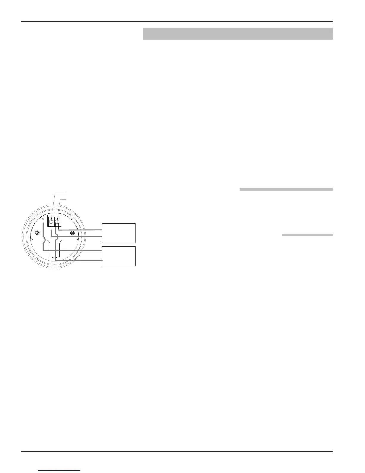
2.6.2 Setting Up for Bench Configuration
The ECLIPSE transmitter can be configured at a test
bench by connecting a 24 VDC power supply directly to
the transmitter terminals as shown in the accompanying
diagram. An optional digital multimeter is shown if cur-
rent measurements are desired.
NOTE: Current measurements taken at these test points is an
approximate value. Accurate current readings should be
taken with the digital multimeter in series with the loop.
1. When using a HART communicator for configuration, a
minimum 250 Ω line load resistance is required. See the
HART communicator manual for more information.
2. The transmitter can be configured without the probe.
(Disregard the error message due to the unattached probe.)
3. After entering the last value, allow 10 seconds before
removing power from the transmitter. This allows the
transmitter to store values.
Current Meter
+
–
Test
Current Meter
Power Supply
24 VDC
–
+
(-) negative
(+) positive
Model 705 with Test Meter