Grove Published 11-10-2014, Control # 524-00 3-3
RT880E SERVICE MANUAL ELECTRIC SYSTEM
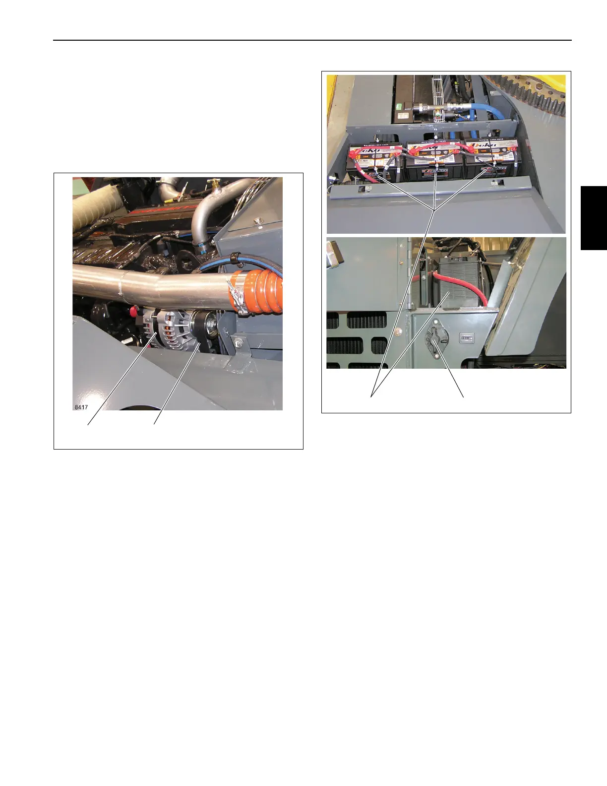
Alternator
The alternator (Figure 3-2) is mounted on the engine and is
belt driven. It is a 145 ampere alternator with an integral
transformer - rectifier unit. When the engine is running, and
the alternator is turning, the alternator’s 12-volt output
terminal supplies the crane’s electrical circuits. The output
terminal also supplies the voltage to recharge the batteries
and maintain them at a full state of charge.
Batteries
The batteries are located in a box on the left side of the crane
behind the hydraulic oil cooler. The batteries are the
maintenance free type and completely sealed except for a
small vent hole in the side. The vent hole allows what small
amount of gases that are produced in the battery to escape.
On some batteries, a test indicator located on the top of the
battery is used to determine if the battery can be tested in
case of a starting problem.
A Battery Disconnect Switch is located on the side of the
battery box (Figure 3-3). To disconnect the batteries, wait
two minutes after turning Ignition Switch OFF and then turn
the Battery Disconnect Switch to OFF. Turn the switch to ON
to connect the batteries.
Cab Electrical Panel
The cab electrical panel (7, Figure 3-4) contains the cab and
superstructure relays, fuse box, wiring harness connector
bulkhead, RCL module, RCL Override switch, and the fast
pulse buzzer alarm. It is located inside the crane cab, behind
the operator’s seat. Access is gained to the back of the panel
by removing the two screws (4) (Figure 3-4) securing the
panel cover.
The two accessory relays (10, 11) (Figure 3-4) behind the
cab electrical panel control power to fuses 9 - 20 in the fuse
box. The coils of the accessory relays are energized when
the ignition switch is at the RUN or ACC position.
The fuse box (3) (Figure 3-4) in the cab electrical panel
contains twenty fuses. Fuses 1 - 5 are energized when the
battery is connected. When the battery is connected and the
ignition switch is at the RUN position, fuses 6 - 8 are
energized, fuses 9-12 are energized through ACC relay #1,
and 13-20 are energized through ACC relay #2.
NOTE: The cab control modules and RCL module are not
serviceable; contact Crane Care Customer Service
with any service or repair questions about the mod-
ules.
FIGURE 3-2
Alternator Alternator Belt
FIGURE 3-3
Battery Disconnect Switch
Batteries
 Loading...


