HYDRAULIC SYSTEM RT880E SERVICE MANUAL
2-46 Published 11-10-2014, Control # 524-00
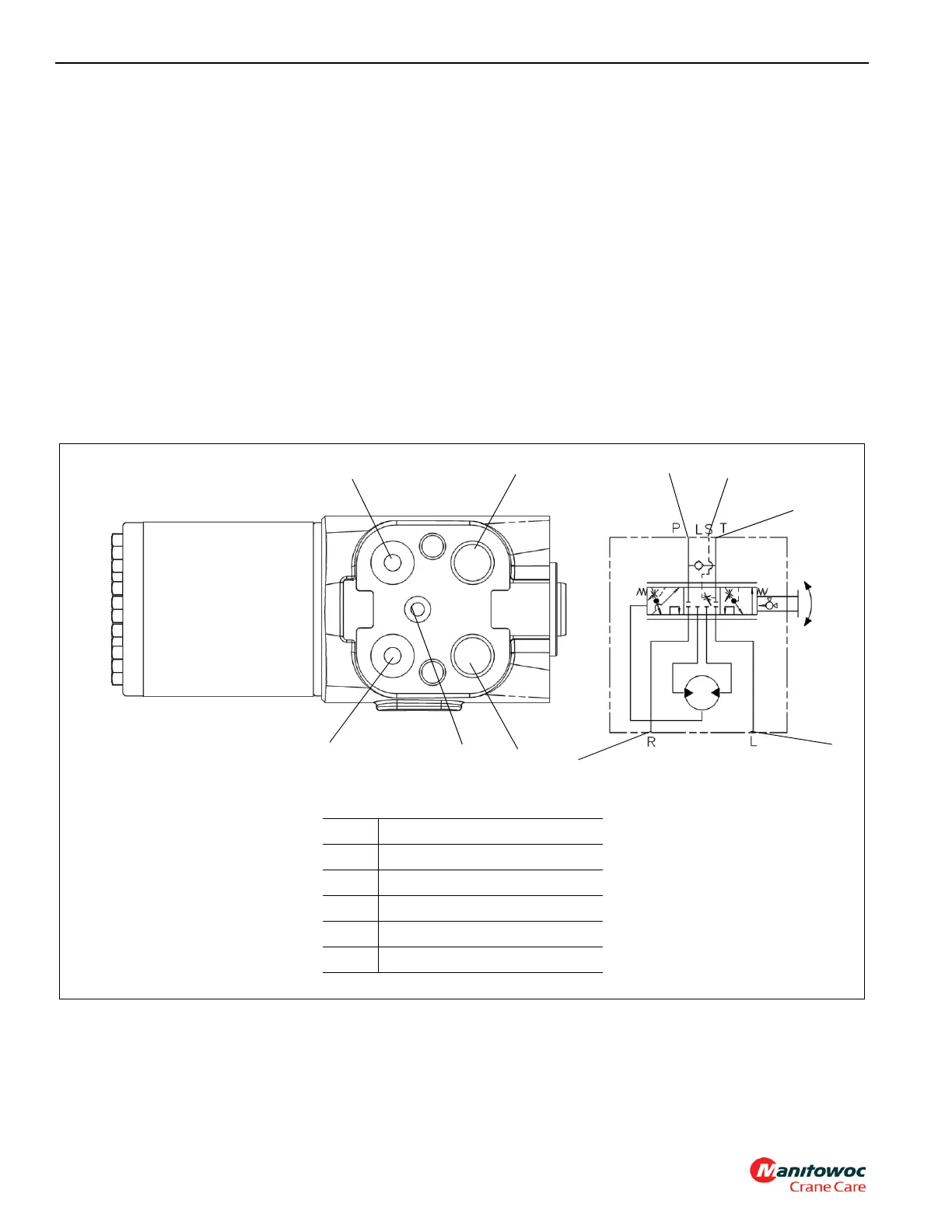
STEERING CONTROL VALVE
Description
The load sense steering control unit (see Figure 2-22)
controls hydraulic flow to the front steering cylinders. It is
located in the steering column of the cab.
Both work ports are connected to the rod side of one steer
cylinder and to the piston side of the other steer cylinder.
Displacement of the valve is 35.9 in³ (588.2 cm³).
Maintenance
Removal
1. Tag and disconnect the electrical connector to the valve.
2. Tag and disconnect the hydraulic hoses from the valve.
Cap or plug the lines and ports.
3. Remove the four mounting bolts and remove the valve
from the steering column.
Installation
1. Secure the valve to the steering column and secure with
the four mounting bolts. Torque bolts; refer to Fasteners
and Torque Values, page 1-15 for proper torque value.
2. Connect the hydraulic hoses to the ports on the valve as
tagged during removal.
3. Connect the electrical connector to the valve as tagged
during removal.
4. Verify proper operation of the valve.
5. Check valve and hydraulic connections for leaks. Make
repairs as needed.
FIGURE 2-22
1
2
1
3
2
4
5
5
3
4
Item Description
1 Pressure Port
2 Tank Port
3 Load Sense Port
4 Steer Right Port
5 Steer Left Port
Valve Hydraulic Schematic