HYDRAULIC SYSTEM RT880E SERVICE MANUAL
2-12 Published 11-10-2014, Control # 524-00
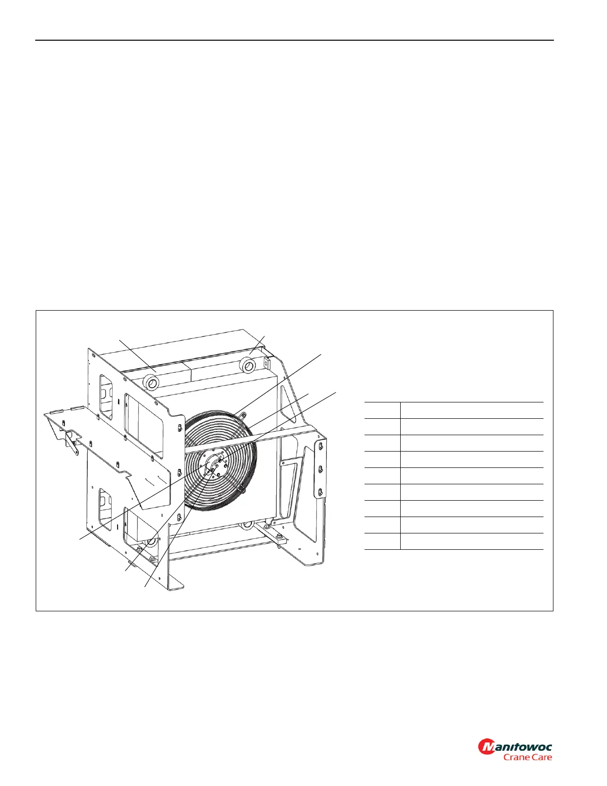
Oil Cooler
An air cooled oil cooler (see Figure 2-5) is located on the left
side of the crane and consists of a transmission oil cooler
and a hydraulic oil cooler.
The fan pulls cool air through the cooling fins on the coolers.
Normally, most hydraulic oil from components is routed
through the oil cooler by way of a return line and on to the
filter in the reservoir. When several hydraulic functions are
being used at one time (i.e., hoisting, lifting, and
telescoping), more oil has to flow through this return line,
causing a pressure buildup. When this pressure reaches
15 psi (103.4 kPa), the normally closed check valve in the
return line (in parallel with the return line through the
hydraulic oil cooler) will open, letting some hydraulic oil
bypass the hydraulic oil cooler and flow directly into the
reservoir filter.
When fewer functions are being used, the pressure in the
system will decrease below 15 psi (103.4 kPa) and the
check valve will close again.
A temperature switch (15, Figure 2-3), located in the tube
that routes return oil to the hydraulic oil return filter in the
reservoir, is part of a circuit that controls the oil cooler fan
motor. The switch is normally closed and will open and cause
the circuit to lose ground when the hydraulic oil temperature
exceeds 120°F (48.8°C). When the circuit loses ground, the
CAN bus system will de-energize the oil cooler solenoid
valve, allowing pressurized oil from Pump No. 1 to flow to the
oil cooler fan motor.
A second temperature switch located in the inlet tube of the
transmission oil cooler, is part of a circuit that will alert the
operator to a high transmission oil temperature condition.
The switch is normally closed and will open and cause the
circuit to lose ground when the transmission oil temperature
exceeds 200°F (93°C). When the circuit loses ground, the
CAN bus system will turn on power to illuminate the
Transmission Warning Indicator in the gauge display in the
operator’s cab. See Section 3 - Operating Controls and
Procedures, in the Operator Manual for details of the
Transmission Warning Indicator.
FIGURE 2-5
Item Description
1 Transmission Oil Cooler
2 External Drain Port
3Fan
4 Hydraulic Oil Cooler
5 Inlet Port
6 Motor
7 Shroud
8Outlet Port
1
2
3
4
5
6
7697
7
8