Grove Published 11-10-2014, Control # 524-00 8-35
RT880E SERVICE MANUAL UNDERCARRIAGE
Extension Cylinder
Description
Two outrigger extension cylinders are utilized within each
outrigger box assembly. The extension cylinders provide the
force for the outrigger beam’s horizontal movement. The
cylinder weighs approximately 100 lb (45.3 kg).
Maintenance
NOTE: Refer to Outrigger Extension Cylinder, page 2-91
for Disassembly and Assembly of the cylinder.
Removal
1. Remove the outrigger beam. Refer to Outrigger Beam,
page 8-31.
2. Remove the cotter pin and clevis pin securing the rod
end of the extension cylinder to the outrigger beam.
3. Pull the extension cylinder from the outrigger beam until
the hydraulic hoses on the rod end of the cylinder can be
accessed. Tag and disconnect the hoses from the rod
end of the cylinder. Cap or plug all openings.
4. Remove the cylinder.
Installation
1. Place the cylinder in the beam.
NOTE: Keep hydraulic fittings and hoses close to angles
shown (Figure 8-34) and as low as possible to pre-
vent rubbing with the beam top plate and side
plate, and for proper tracking during beam exten-
sion and retraction.
2. Position the extension cylinder so the hydraulic ports on
the rod end of the cylinder can be accessed. Connect
the hydraulic hoses to the ports as tagged during
removal.
3. Push the cylinder into the outrigger beam. Align the cyl-
inder rod with the clevis in the beam. Apply anti-seeze to
the clevis pin and secure in place with the clevis pin and
cotter pin.
4. Install the outrigger beam. Refer to Outrigger Beam,
page 8-31.
Functional Check
1. Activate the hydraulic system; extend and retract the
outrigger.
2. Observe the operation of the outrigger beam.
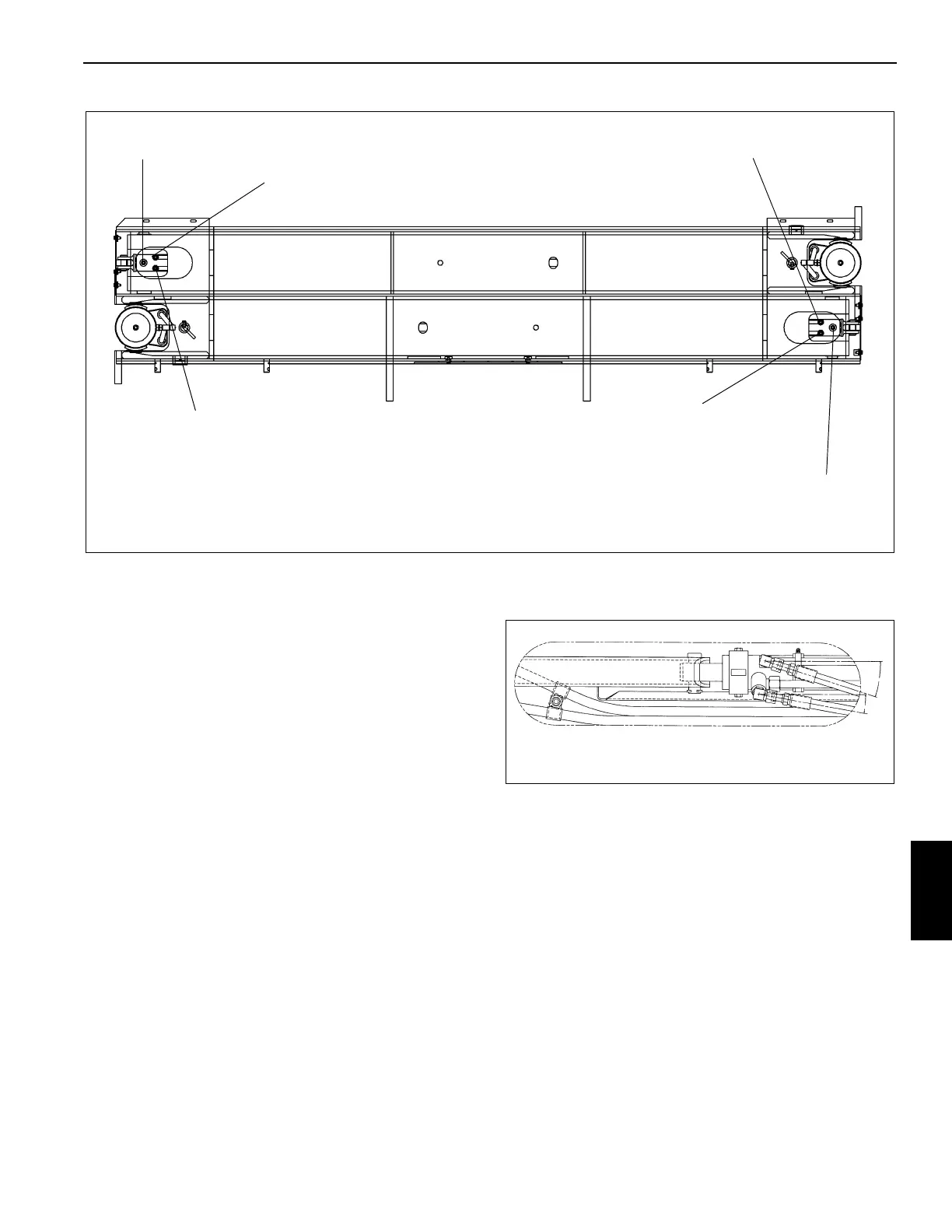
Jack Cylinder and Extension Cylinder Retract Port
Jack Cylinder Extend Port
Extension Cylinder Extend Port Jack Cylinder Extend Port
Jack Cylinder and Extension Cylinder
Retract Port
Extension Cylinder Extend Port
FIGURE 8-33
 Loading...


