HYDRAULIC SYSTEM RT880E SERVICE MANUAL
2-42 Published 11-10-2014, Control # 524-00
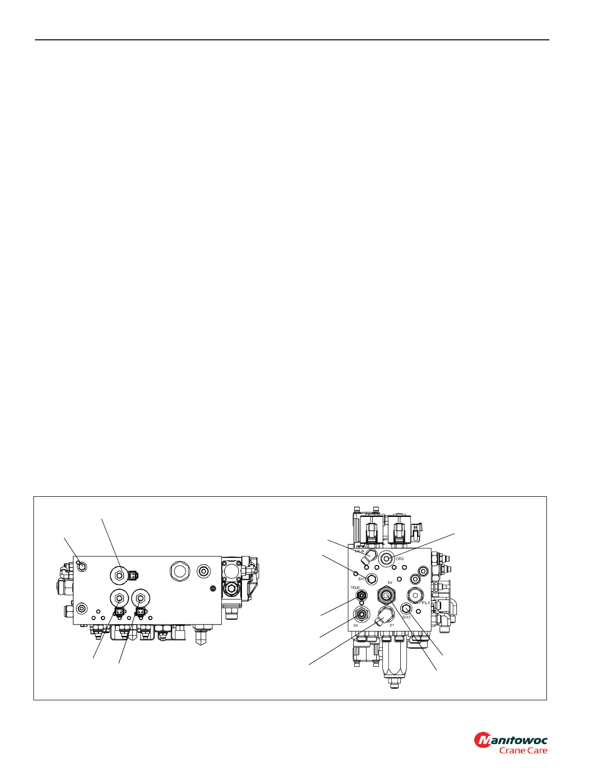
FRONT STEER/SWING/BRAKE MANIFOLD
Description
The front steer, swing and brake manifold (Figure 2-21)
houses cartridge components that control the front steer,
pilot functions, swing brake release and the telescope hose
reel. It is located on the outside of the right hand
superstructure side plate under the removable valve cover.
The manifold has two inlets, one for the piston pump No. 1
and one for the gear pump No. 2. The end opposite the bolt
on swing directional valve houses the low pressure case
drain that manifolds low pressure oil from swivel port 10, and
returns it to the tank. It is located on the outside of the right
hand superstructure side plate under the removable valve
cover.
Oil from pump No. 2 enters the P2 inlet port from port 5 of
the hydraulic swivel. The oil flows to the front steer flow
control valve to a second flow control valve for the swing
directional valve which is bolted onto the front steer, swing
and accessory manifold. A main inlet relief protects pump
No. 2. The front steer flow control valve is a load sense
priority type flow control valve. On a load sense signal from
the cab steering control valve, the spool shifts, directing
controlled flow to the cab steering control unit. The load
sense port maintains a constant 861.8 kPa/8.6 bar (125 psi)
standby pressure. Any excess flow is directed to the swing
section. The circuit is protected by a load sense relief valve
incorporated in this section. The second flow control valve is
unloaded when the swing directional valve is in neutral.
When the swing is actuated, the valve delivers a maximum
of 95 lpm (25 gpm).
Pump No. 1 enters the P1 inlet through swivel port 7. The oil
flows first through a 100 mesh screen then supplies three
pressure reducing valves and five two position three way
solenoid valves in parallel for the pilot and hose reel
functions. It has a separate connection, before the 100 mesh
screen that supplies the service brake charge valve.
One pressure reducing valve and solenoid are used for the
swing brake and brake release, one pressure reducing valve
feeds solenoids for the controllers and telescope two stage
relief, and one pressure reducing valve is used for the hose
reel motor and hose reel brake. The pump load sense and
(4) load sense shuttle checks are required to bring the pump
on and off stroke when the hose reel or telescope two stage
relief valve is selected and located in this manifold. All other
pilot functions use the pump standby pressure to fully
operate at engine idle.
Maintenance
Removal
1. Tag and disconnect all of the electrical connectors or
manual control levers.
2. Tag and disconnect the hydraulic lines from the valves.
Cap or plug the lines and ports.
NOTE: The swing/steer/brake valve bank weighs
approximately 69.6 lb (31.6 kg).
3. Remove the bolts and lockwashers securing the valve
bank and remove the valve bank.
Installation
1. Place the valve bank on the superstructure side plate
and fasten it with the capscrews and washers. Torque
capscrews; refer to Fasteners and Torque Values, page
1-15 for proper torque value.
2. Connect the hydraulic lines to the valves as tagged
during removal.
3. Connect the electrical connectors to the valve as tagged
during removal.
FIGURE 2-21
Top View
7392-4
6366-3
Left View
8
40
51
50
48
46
62
49
41
10
47
9