Grove Published 11-10-2014, Control # 524-00 2-57
RT880E SERVICE MANUAL HYDRAULIC SYSTEM
HOLDING VALVES
Description
A bolt-on manifold style holding valve is installed on the
boom lift and luffing jib cylinders. A cartridge style holding
valve is used on each telescope cylinder installed in the
piston side of the cylinder. The counterweight removal
cylinders have two cartridge style holding valves installed in
rod side of each cylinder.
The holding valve provides meter out control, will lock the
cylinder in place, prevent a load from running ahead of the oil
supply, and will relieve excess pressure caused by thermal
expansion.
Lower Lift Cylinder Holding Valve
Removal
1. Lower the boom to below horizontal.
2. Extend the boom to align the access holes in second
and third boom sections.
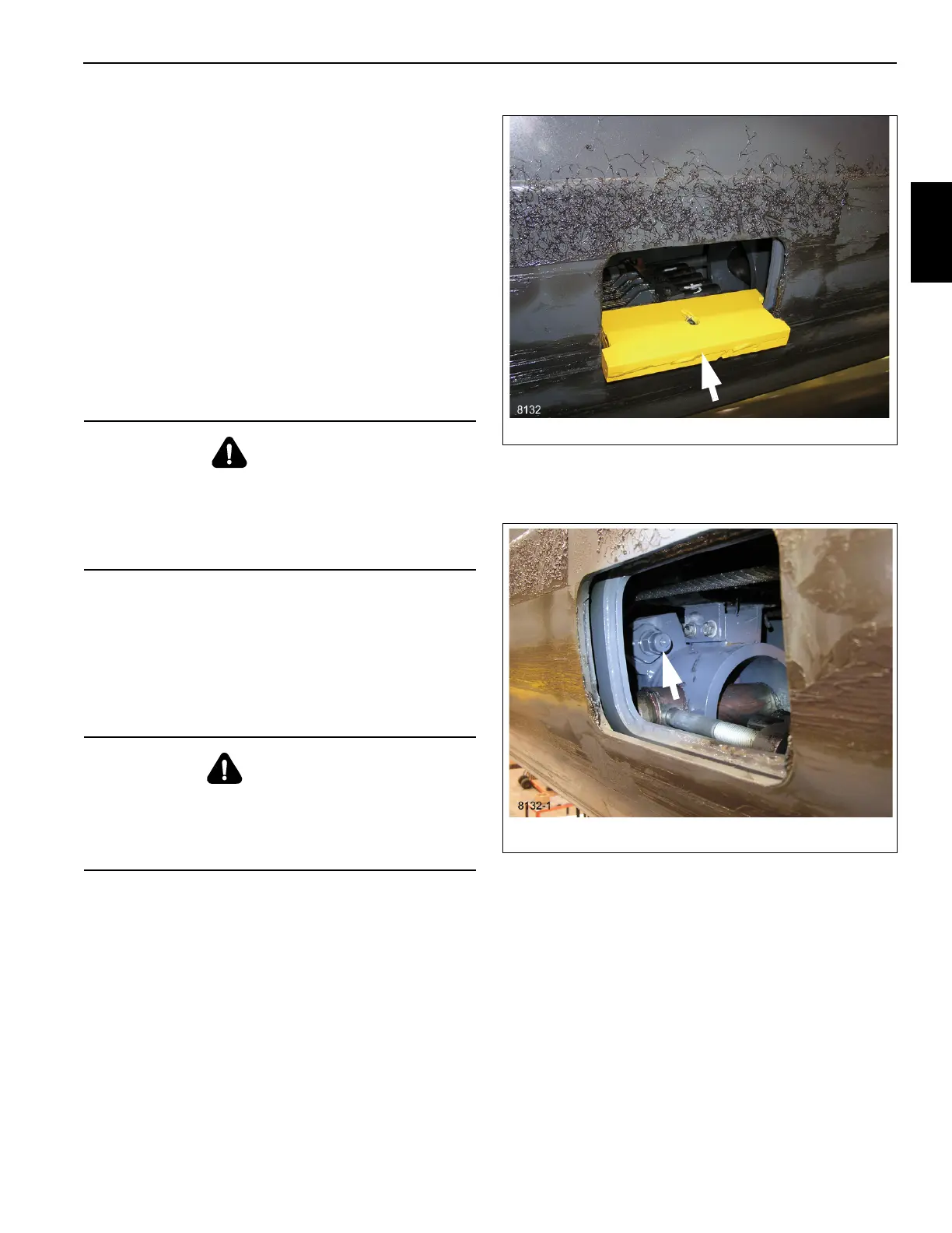
3. Install the telescope hold valve tool, P/N 80041761, see
Figure 2-30. While holding the tool in position have a
helper retract section 3 to lock the tool into place.
4. From the access holes in the opposite side of the boom,
relieve the pressure in the lower telescope cylinder by
loosening the bleed plug, (35, Figure 2-43).
5. Unscrew holding valve from its port block. (See
Figure 2-31 and Figure 2-43.)
Installation
1. Check the inside of the port block for any sharp edges or
burrs and remove as necessary with emery cloth.
2. Install new O-rings onto the holding valve.
3. Lubricate the holding valve and O-rings with clean
hydraulic oil.
DANGER
Pinch Point Hazard!
Before accessing the holding valve install the telescope
hold valve tool to prevent section 3 from retracting into
section 2 when the holding valve is removed. Serious
injury may result.
WARNING
Flying Object Hazard!
The holding valve can fly with explosive force if the
hydraulic pressure is not relieved. Serious injury may
result.