Grove Published 11-10-2014, Control # 524-00 6-15
RT880E SERVICE MANUAL SWING SYSTEM
NOTE: The hydraulic swivel weighs approximately 213 lb
(97 kg). The hydraulic, water, and electrical swivel
combined weigh approximately 239 lb (108 kg).
9. On the bottom of the swivel, bend the retainer tabs away
from the bolt heads. Remove the capscrews and cap-
screw retainers securing the two retainer plates to the
spool. Remove the retainer plates from the spool and
the lugs on the carrier frame.
NOTE: It may be necessary to remove some drive line
components to remove the swivel.
10. Position an adequate supporting device beneath the
swivel.
11. Remove the capscrews, washers, and bushings secur-
ing the swivel barrel to the turntable base plate and
lower the swivel to the ground.
Installation
NOTE: The hydraulic swivel weighs approximately 213 lb
(97 kg). The hydraulic, water, and electrical swivel
combined weigh approximately 239 lb (108 kg).
1. Raise the swivel into position.
2. Secure the hydraulic swivel to the turntable base plate
with the bushings, capscrews and washers. Torque cap-
screws; refer to Fasteners and Torque Values, page 1-
15 for proper torque value.
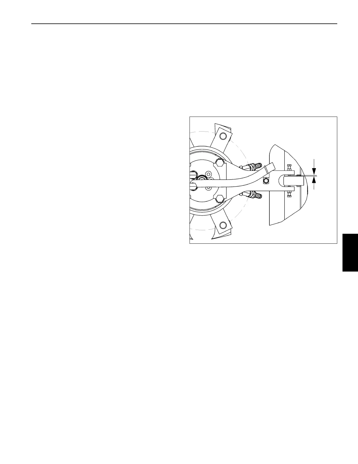
NOTE: Allow a 1/32' (1 mm) max gap between bolt and the
retaining lug on the frame. Do not tighten bolt
against lug (Figure 6-7).
3. Position the two retainer plates on the hydraulic swivel
spool ensuring they engage the lugs on the carrier
frame. Secure the retainer plates with the capscrews
and capscrew retainers. Apply Loctite® 271 to the bolt
threads. Torque the bolts 199 lb-ft (270 Nm). Bolt head
flats must align with retainer tabs. Bend all the retainer
tabs to make contact with the bolt heads. Snug the
retainer plate capscrews against the lugs on the carrier
frame and tighten the locking nuts.
4. If removed, install the electrical swivel. Refer to Electri-
cal Swivel, page 6-16. Connect the swivel wiring har-
ness connectors to the carrier receptacles and the
ground wire to the mounting bracket on the carrier
frame. Use the bolt and star washers taken off at
removal. Make sure the ground connection is clean and
has good metal to metal contact. Spray the connection
with a battery terminal protectant such as Deka Battery
Terminal Protection spray, Grove P/N 9999102423.
5. Install the clamp, lockwasher, flat washer and capscrew
to the bottom of the swivel retainer plate securing the
wiring harness.
6. Connect the hydraulic lines and water lines to the spool
of the hydraulic swivel as tagged during removal.
7. Connect the hydraulic lines to the hydraulic swivel case
as tagged during removal.
8. Connect the water lines to the water swivel case as
tagged during removal.
9. Remove the blocking material from the lift cylinder.
10. Activate all systems; cycle all functions and observe for
proper operation and any leakage.
Two Port Water Swivel
Description
The two port water swivel allows engine coolant to flow from
the carrier-mounted engine to the hot water heater in the
operator’s cab. Through an internally drilled passage in the
14 port hydraulic swivel spool, coolant is transferred to a
circumferential groove on the water spool exterior. This
groove corresponds with a mating port on the outer case of
the water swivel. The spool grooves are separated by a quad
ring/telflon bronze ring seal. The lip seal prevents coolant
from leaking externally. Return engine coolant flow from the
hot water heater is accomplished in the same manner
through the opposite port of the water swivel.
Maintenance
Removal
1. Perform steps 1 thru 4 of the removal procedure under
Hydraulic Swivel, page 6-14.
2. Remove the electrical swivel. Refer to removal proce-
dure under Electrical Swivel, page 6-16.
3. Tag and disconnect the lines from the case of the water
swivel. Cap or plug all lines and openings.
FIGURE 6-7
1.0 mm
(0.031 in)
 Loading...


