Grove Published 11-10-2014, Control # 524-00 3-13
RT880E SERVICE MANUAL ELECTRIC SYSTEM
7. Remove the bolts holding the starter to the mounting
pad. Remove the starter.
Installation
1. Place the starter on its mounting pad. Secure the starter
with the bolts. Torque the bolts to 32 lb-ft (43 Nm).
2. Connect the electrical leads to the terminals as tagged
during removal.
3. Connect the batteries.
4. Install the ECM power fuse.
5. Turn the battery disconnect switch to the ON position.
6. Close the engine compartment.
Check
1. Try to start the engine. Verify the starter starts the
engine.
2. Start engine again, and listen for starter noises. Verify
there is no abnormal noise indicating the starter’s gear is
meshing properly with the flywheel, that the starter’s
gear hasn’t remained engaged to the flywheel after the
ignition switch is in the ignition (run) position, or some
other problem. Install starter properly as needed.
Battery Replacement
Removal
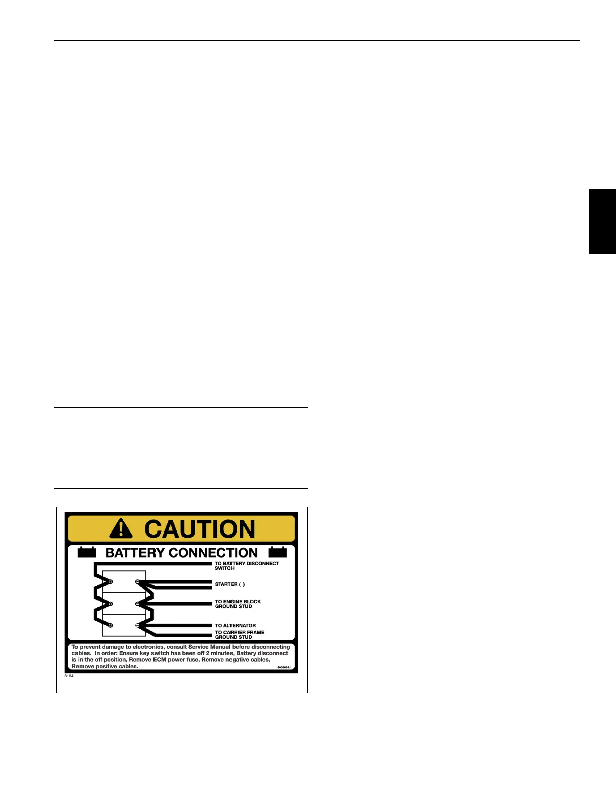
1. Ensure that the key switch has been off for 2 minutes.
2. Turn the battery disconnect switch to the OFF position.
3. Remove the ECM power fuse.
4. Remove negative battery cables.
5. Remove positive battery cables.
6. Remove the nuts and washers from the bracket hold
down rods. Remove the hold down bracket.
7. Remove the batteries.
Installation
1. Place the batteries in the battery box.
2. Install the hold down bracket so it can hold down the bat-
teries. Secure the bracket (and batteries) to the bracket
hold down rods with nuts and washers.
3. Connect leads to the battery terminals starting with the
positive terminals.
4. Close the battery box cover.
5. Install the ECM power fuse.
6. Turn the battery disconnect switch to ON.
7. Verify replacement batteries work by starting crane’s
engine and operating various crane components.
Relay Panel Component Replacement
Accessory Relay
1. Turn the ignition switch to the OFF position.
2. Wait two minutes.
3. Turn the battery disconnect switch to the OFF position.
4. Working behind the operator’s seat, remove the hard-
ware securing the panel cover and remove the cover.
5. Tag and disconnect the electrical leads from the suspect
relay.
6. Remove the hardware securing the suspect relay to the
relay panel assembly. Remove suspect relay.
7. Install replacement relay on relay panel and secure it
with attaching hardware.
8. Connect the electrical leads to the relay as tagged dur-
ing removal.
9. Position the cover on the panel and secure with the
attaching hardware.
10. Connect the batteries.
11. Turn the battery disconnect switch to the ON position.
12. Verify proper installation by operating all components
involved with the replacement relay verifying they all
work.
CAUTION
To avoid possible engine fault codes and undesirable
operation, ensure the keyswitch has been off 2 minutes
before disconnecting batteries.
Disconnect batteries if machine will be inactive for over 24
hours.

 Loading...


