Grove Published 11-10-2014, Control # 524-00 5-9
RT880E SERVICE MANUAL HOISTS AND COUNTERWEIGHT
HOIST DRUM ROTATION INDICATOR
SYSTEM
Description
The hoist drum rotation indicator system (Figure 5-6) is an
electrically operated system that provides the operator with a
touch indication of drum rotation so the operator will know if
and at what speed the hoist drum is rotating, even under the
most distracting conditions.
The drum rotation indicator system consists of the drum
rotation sensor and thumb thumper solenoid. The drum
rotation sensor is located on the hoist (Figure 5-6) and
senses the rotation of the primary drive end driven gear. The
pulsing thumb thumper solenoid is located in the applicable
hoist control lever handle (Figure 5-6). Actuation of the
thumb thumper is controlled by the Can-Bus system from
input supplied by the drum rotation sensor. The thumb
thumper solenoid provides feedback proportional to the hoist
line speed by pulsing the rubber button on top of the hoist
controller. The thumb thumper will cease operation at high
line speeds to prevent damage to the solenoid.
Maintenance
General
Proper circuit operation can be checked for each individual
electrical component. If a malfunction occurs within the
system, repairs should be limited to finding and replacing the
faulty component(s). To determine which component is at
fault, refer to the troubleshooting section of your CAN bus
CD.
Troubleshooting
NOTE: This machine incorporates a CAN bus Multiplex
system. In order to effectively troubleshoot the
electrical system, you will need a Windows-based
PC, CAN-link service software (9999102409), and
a connection cable (9999102296). The CAN-Link
service software and connection cable are avail-
able through Manitowoc Crane Care to those ser-
vice technicians who have attended the Grove New
Technology training course.
Removal
1. Disconnect the wire at the drum rotation sensor.
2. Loosen the jam nut securing the drum rotation sensor
and then remove the sensor.
Installation
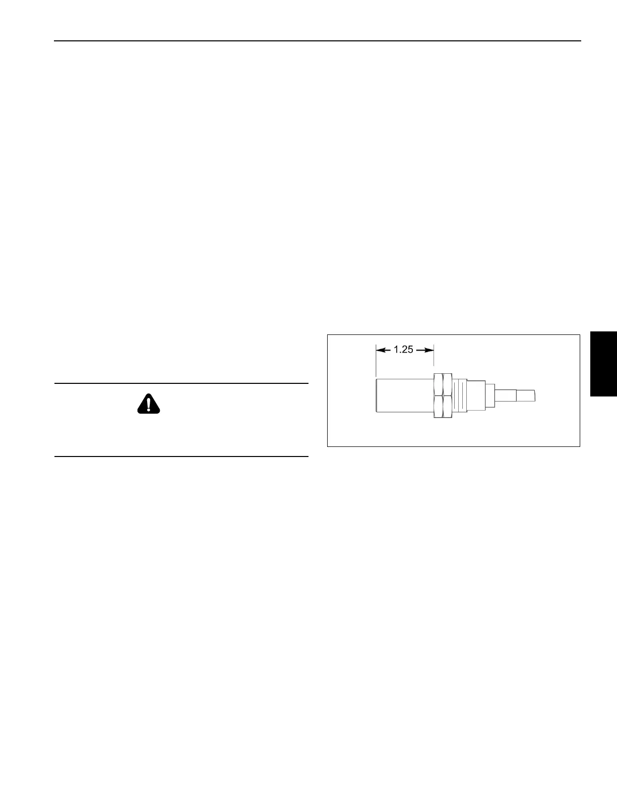
1. Turn the two jam nuts on the drum rotation sensor to pro-
duce 1.25 in. (31 mm) installed length of threads mea-
sured from the bottom of the sensor to the bottom jam
nut (Figure 5-5).
2. Hold the bottom jam nut with a wrench and tighten the
top jam nut against it. Check the length of threads to be
sure the installed length did not change.
3. Apply a small amount of general purpose grease to the
threads and install the drum rotation sensor into the
motor end-plate.
4. Using the outer jam nut, tighten the sensor until just
snug to avoid damage to the sensor.
5. Connect the wire to the drum rotation sensor.
DANGER
Disconnect the batteries before performing any
maintenance on this system. Serious burns may result
from accidental shorting or grounding of live circuits.

 Loading...


