GROVE Published 10-21-2010, Control# 198-04 7-29
5540F/YB5515 SERVICE MANUAL TRANSMISSION AND TORQUE CONVERTER
1. Place the drive plate and reinforcing plate
(1 Figure 7-17) onto the torque converter.
2. Place the torque converter alignment tool A
(Figure 7-18) over the torque converter shaft, making
sure that the tool locates in two of the converter bolt
holes as shown. It is important to note that the converter
drive tube must be protected against damage or
contamination at all times.
3. Apply Loctite 242 to the threads of bolts 2 and install four
of the bolts, attaching the drive plate to the torque
converter. Tighten the bolts to 62 lb-ft (84 Nm). Remove
the alignment tool and install the remaining two bolts.
Tighten to a torque of 62 lb-ft (84 Nm).
4. Locate the torque converter and drive plate assembly on
the flywheel. Apply Loctite 242 to bolt 3 and install the
bolts to attach the drive plate to the flywheel. Check the
converter run-out as shown in B of Figure 7-19, which
should not exceed 0.015 inches (0.33 mm). Adjust as
necessary.
5. Tighten the drive plate mounting bolts 3 to a torque of 14
lb-ft (10 Nm).
Installing without Alignment Tool (Optional)
1. Assemble the drive plate and reinforcing plate
(1, Figure 7-17) to the torque converter using bolts 2.
Apply Loctite 242 to the bolts and only finger tighten at
this time.
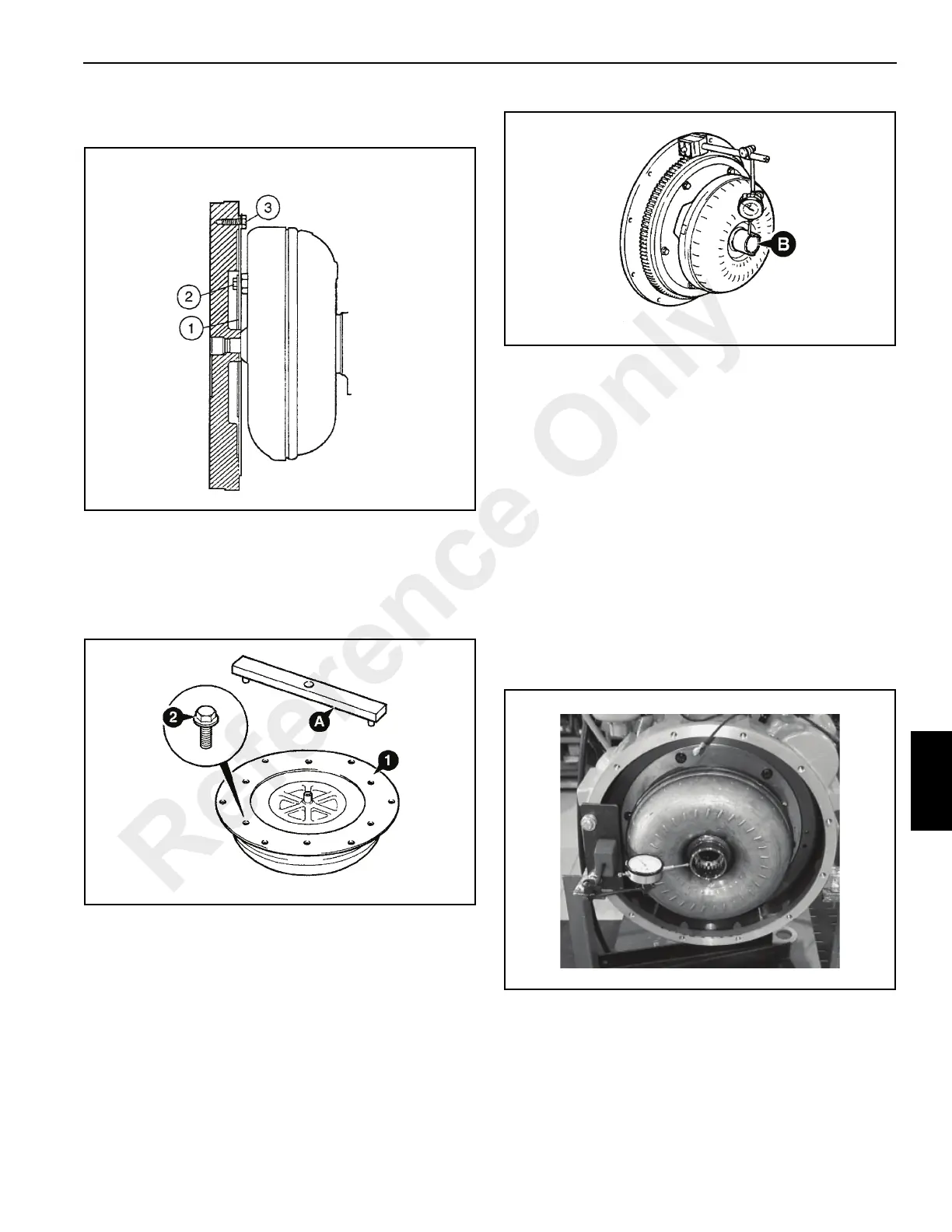
2. Install the torque converter and drive plate assembly to
the engine flywheel, fasten with mounting bolts 3. Check
the alignment of the torque converter to the flywheel
using a dial indicator held in position against the
converter hub (Figure 7-20). The torque converter must
be centered on the flywheel within 0.015 in (0.33 mm).
When correct, mark the position of the flywheel and
drive plate, then remove the drive plate and annulus
from the flywheel.
3. Tighten bolts to a torque of 62 lb-ft (84 Nm).
4. Install the torque converter and drive to the engine
flywheel, aligning the drive plate with the alignment
marks. Recheck centering on the flywheel. Coat the
threads of bolts with Loctite 242 and install them.
Tighten the bolts to a torque of 14 lb-ft (19 Nm).
FIGURE 7-20
p-centering
Centering Check
Reference Only
 Loading...


