GROVE Published 10-21-2010, Control# 198-04 9-11
5540F/YB5515 SERVICE MANUAL
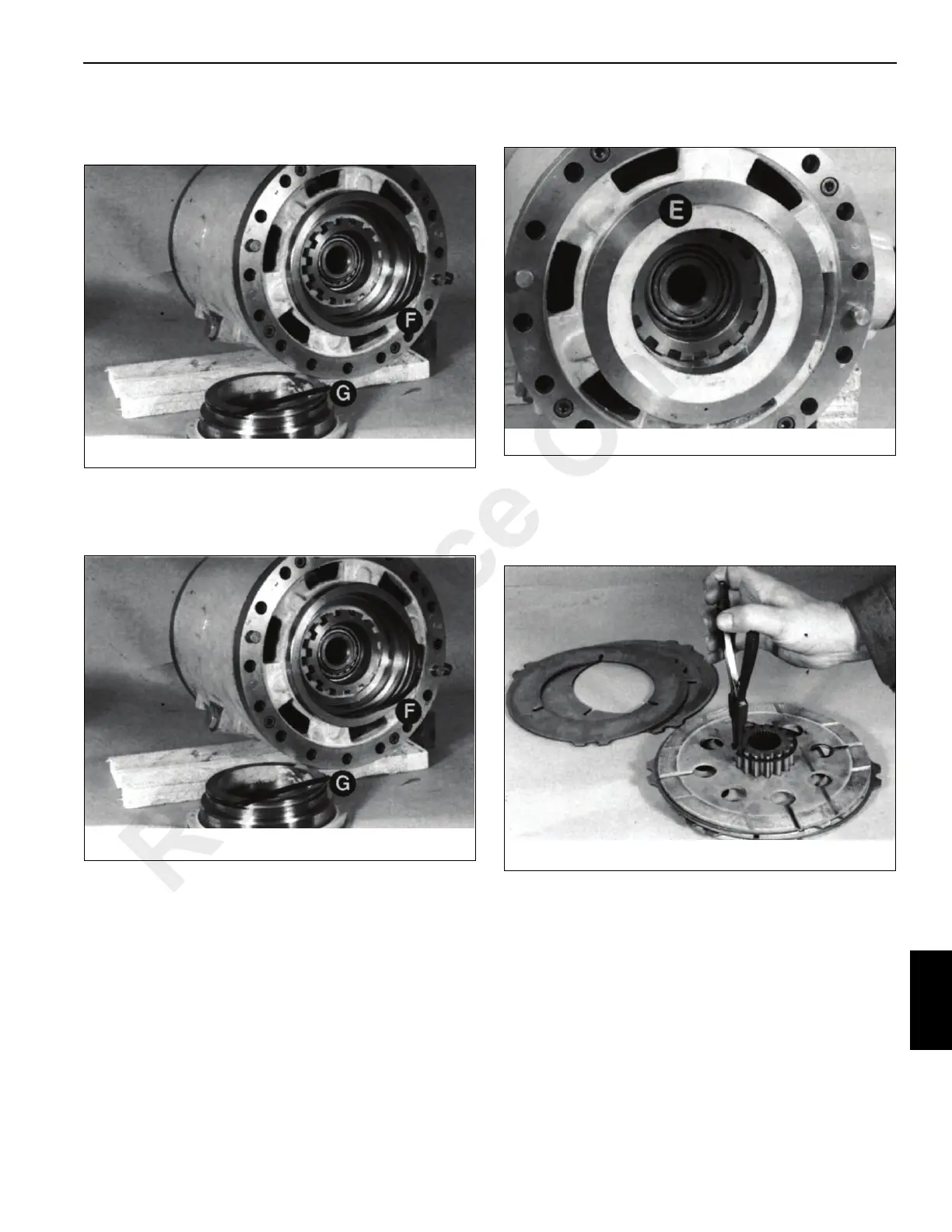
8. Remove and discard seals F and G Figure 9-21. Inspect
the housing for damage and scoring. Nicks or cuts in the
seals may be responsible for loss of brake fluid.
Assembly
1. Install new seals F and G Figure 9-22. Make sure they
seat squarely in their grooves.
2. Carefully press piston E Figure 9-23 all the way into its
housing.
3. Assemble the friction plates and counterplates onto the
carrier. If the original brake pack is being reused, return
the plates to their original positions (see Disassembly
step 3). Soak new friction plates in gear oil before
assembly. Install retaining ring Figure 9-24.
Reference Only
 Loading...


