STEERING SYSTEM 5540F/YB5515 SERVICE MANUAL
10-26 Published 10-21-2010, Control# 198-04
Assembly
1. Install new gland seal 14 Figure 10-32 using the special
and installation tool as follows:
NOTE: The size (diameter) and position of pins is
determined by the diameter and radial width of the
gland seal being installed.
The pins are screwed into threaded holes in the
tool body, the spacing of the holes is designed to fit
small and large diameter gland deals.
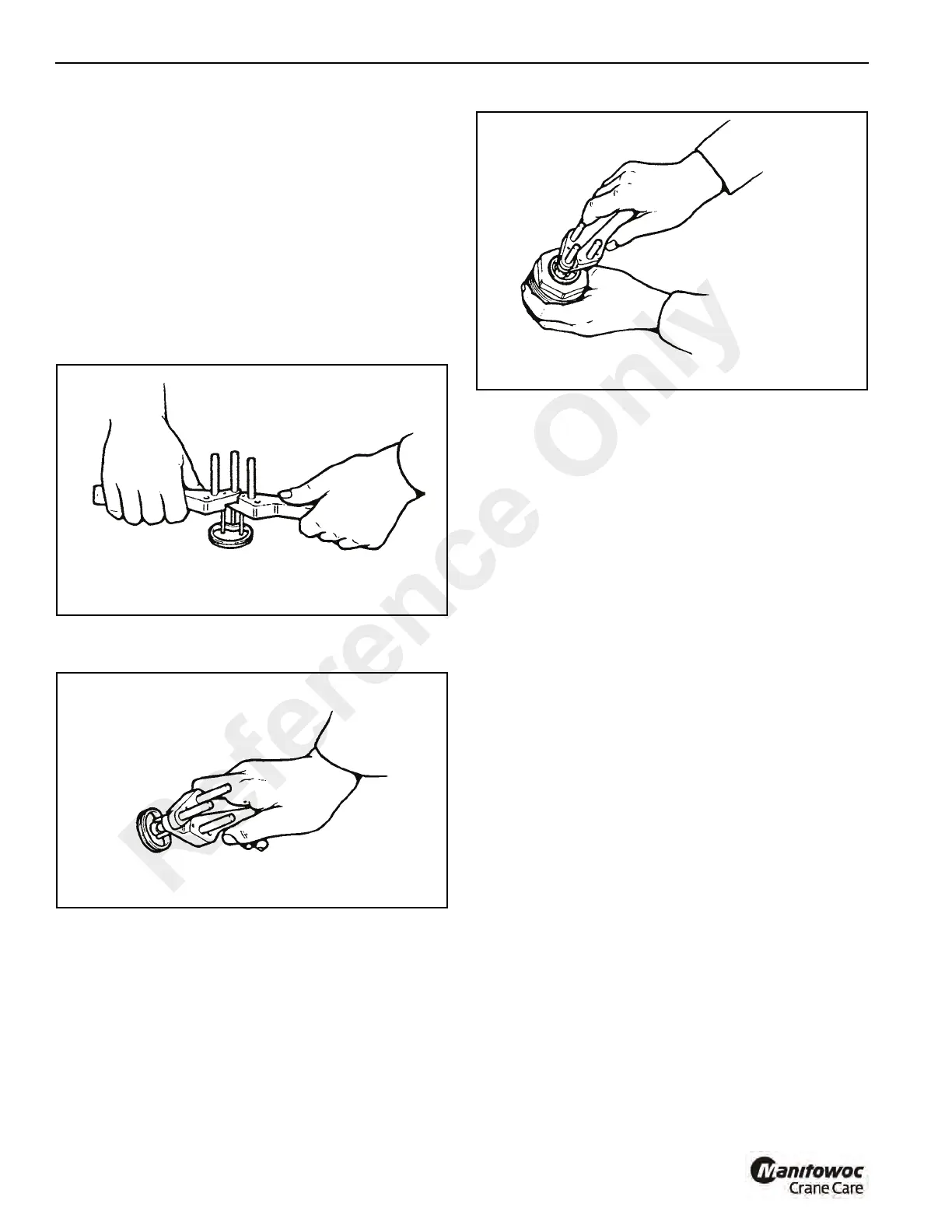
a. Open the tool Figure 10-33 and insert the new gland
seal. The seal must be installed behind the two front
pins but in front of the rear pin as shown.
b. Close the tool Figure 10-34. The seal must form a
kidney shape.
c. Locate the seal in the end cap groove Figure 10-35.
When the seal is in position, open the tool to release
the seal. Make sure the seal is correctly installed in
its groove before then remove the tool.
2. Install a new wiper seal 15 Figure 10-32 and new o-ring
12 to end cap 13. The lip of the wiper seal must be facing
out.
3. Apply Loctite Activator T to threads of the end cap and
cylinder barrel. Allow the activator to dry for 15 minutes
before bringing in contact with Loctite.
NOTE: Be sure that lubricants used during assembly do
not come in contact with Loctite.
4. Cover the threads on the cylinder rod to prevent
lubricant from contacting the Loctite.
5. Apply petroleum jelly to the inside bore of the end cap.
Carefully slide the end cap assembly over the end of the
piston rod.
6. Install o-ring 11 into piston 7.
7. Install piston 7 onto cylinder rod 16. Tighten to a torque
of 300 lb-ft (405 Nm).
8. New cylinder rod and piston installed.
If both are required, the following procedure should be
followed:
a. Drill through the piston into the cylinder rod at the
dimension Figure 10-36. Use an undersize drill first
as a guide, drill to a depth of 24 mm. Then using a 6
mm drill bit, drill the hole for the dowel.
b. Remove all swarl and contamination. Insert dowel 8
Figure 10-32 into drilled hole. Make sure threaded
extractor hole is to the outside.
Reference Only
 Loading...


