STRUCTURALS 5540F/YB5515 SERVICE MANUAL
11-22
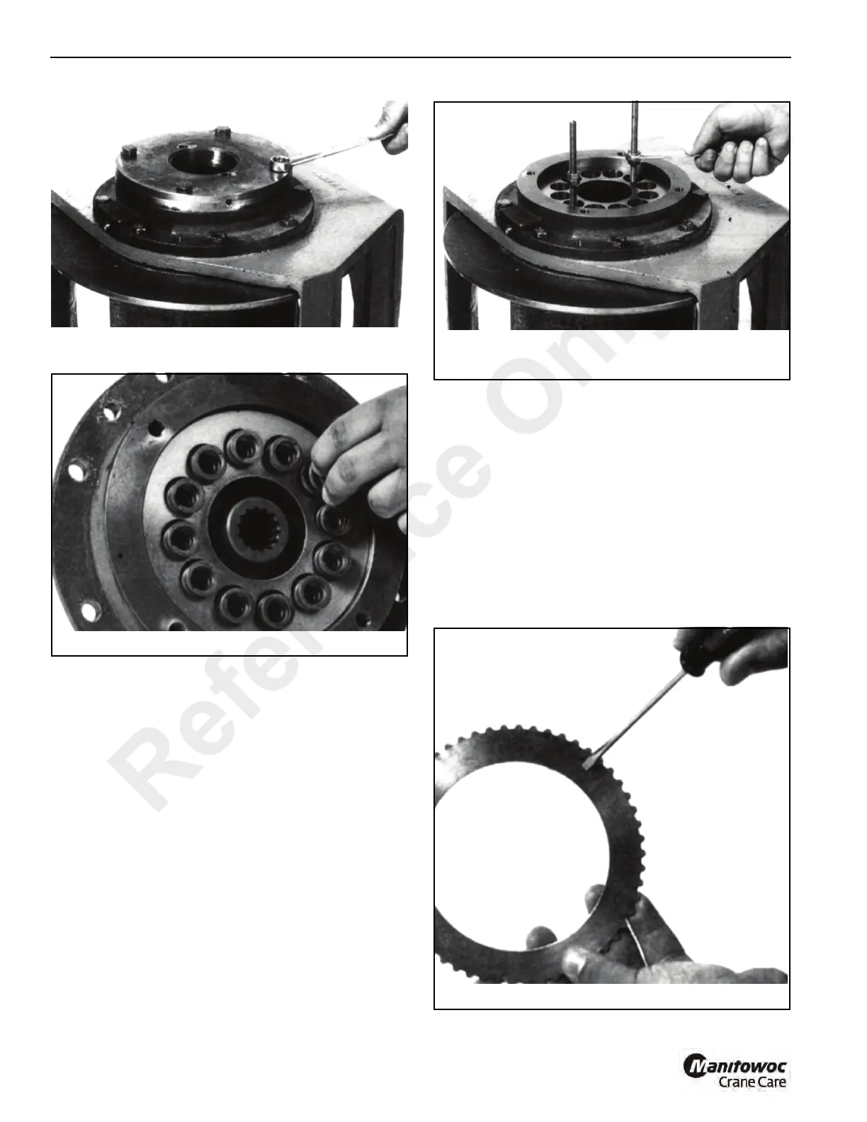
3. Remove the piston by installing two pieces of3/8 NC all-
thread (Figure 11-36) in the bottom of the two spring
pockets. Using jam nuts, screw the all-thread pieces in
evenly until the piston is clear of the housing. An
alternate way of removing the piston is use a portable
power unit or air pressure to pressurized the brake
cavity and blow the piston out of the bore.
4. If one or both of the square seals (8, Figure 11-33)
remain in the bore of the brake housing, remove them.
5. Grasp the brake driver/clutch assembly (items17
through 23, Figure 11-33) and remove it from the brake
housing.
6. Remove the stator plates 7 and friction discs6 from the
brake housing and check them for excessive wear.
Replace if necessary. Be sure to check the top stator
plate (Figure 11-37) for scoring caused by the removal
tools and polish if necessary. Friction discs
(Figure 11-38). should measure no less than 0.055
inches (1.40 mm) thickness and stator plates should
measure no less 0.068 inches (1.72 mm) thickness.
Reference Only
 Loading...


