11-39
5540F/YB5515 SERVICE MANUAL STRUCTURALS
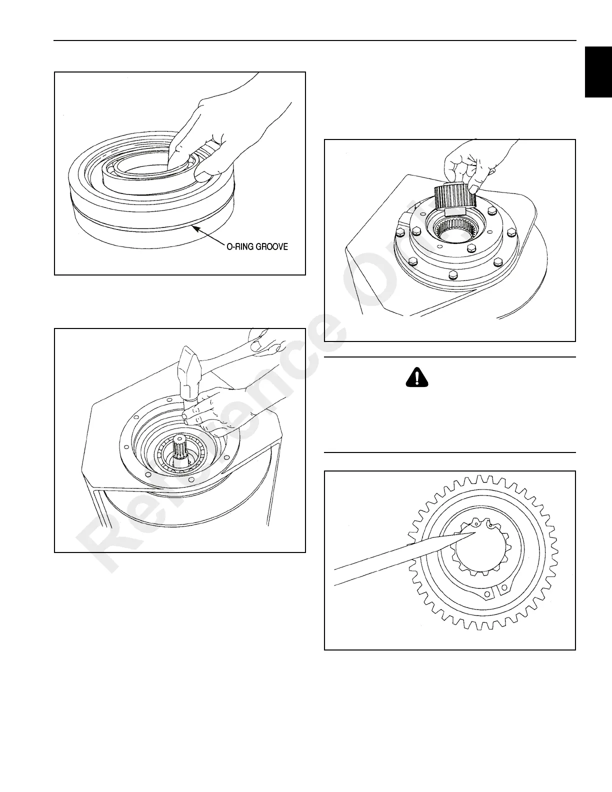
11. Lubricate the O-ring and drum opening with petroleum
jelly or gear oil and install the drum closure
(Figure 11-79) into the drum.
12. Lubricate the pilot, oil seal and bearing surfaces of the
brake cylinder and carefully install brake cylinder into
base and drum.Locate the brake release port toward the
lower rear corner of the base. Install and tighten brake
cylinder capscrews to recommended torque.
13. Install the brake clutch assembly (Figure 11-80) with the
short end of the inner race toward motor.
When installed correctly, the inner race should turn
freely in the opposite direction the drum turns to pull wire
rope in. An easy way to check the rotation is to hold the
outer race in one hand, and rotate the inner race.
If the clutch free wheels in the wrong direction,
disassembly the clutch and reverse the inner race. Refer
to “Brake Clutch Service”, for additional information.
14. If the brake discs are misaligned: preventing the
installation of the clutch, then with a hand pump, apply
750-1000 psi to the brake release port. The brake discs
will move freely with the brake released, permitting
alignment of the discs, brake clutch and input sun gear.
WARNING
Be certain the snap ring (Figure 11-81) is seated in me
groove in the splined bore of the inner race. This snap ring
will keep the brake clutch assembly correctly positioned in
the center of the friction brake pack. Binding of the brake
or brake failure may occur if this snap ring is omitted.
Reference Only
 Loading...


