DKR Drive Controllers Planning the cabinet 5-3
DOK-DIAX03-DKR********-PR02-EN-P
KRDKR
max pressure
min. air flow
p
max
Q
min
DKR02
160
300
DKR04
390
360
Unit
Pa
m
3
h
internal power
loss
heatsink
P
V(ext)
external power
loss
DKR 02/03
P
V(int)
air vent
internal power
loss
heatsink
P
V(ext)
external power
loss
DKR 04
P
V(int)
air vent
air flow Q
air flow Q
press.
p
press.
p
160
300
DKR03
50 Hz
60 Hz
db(A)
noise
db(A)
Symbol
68
68
68
76,1
68
75,5
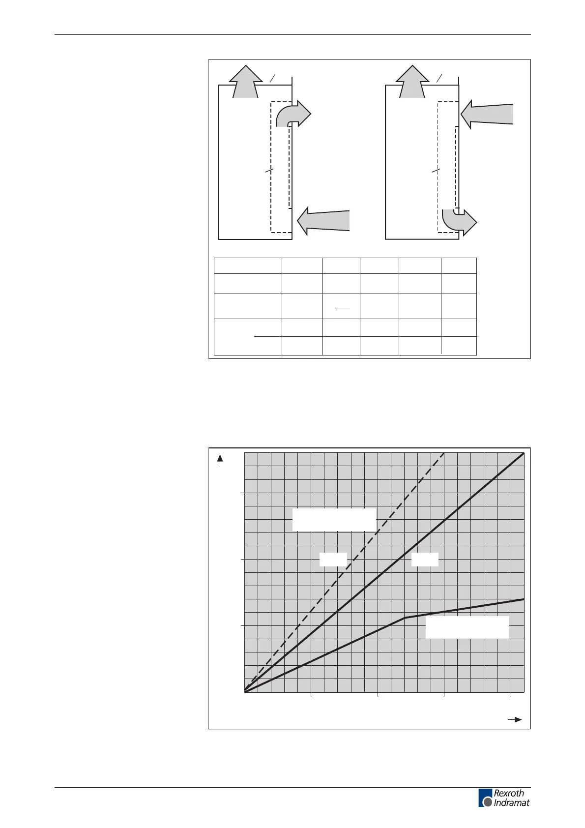
Fig. 5-2: Energy dissipated, air flow data and noise emissions
The energy dissipated both internally and externally is load-dependent. To
correctly dimension the cabinet or cooling equipment, it is necessary to
know the individual energy losses. Using the nominal current of the motor
used and the switching frequencies which have been set, it is possible to
estimate the energy losses of the DKR using the following diagram:
50 100
0.5
1
motor rated current in A
power loss in kW
DGVerDKR
150
8 kHz 4 kHz
external power loss
P
V(ext)
200
1.5
internal power loss
P
V(int)
Fig. 5-3: Determining energy losses
LSA Control S.L. www.lsa-control.com comercial@lsa-control.com (+34) 960 62 43 01