6-2 Planning the electrical connections DKR Drive Controllers
DOK-DIAX03-DKR********-PR02-EN-P
6.3 Positions of the connectors, pin configurations and lead
cross sections
DIAX03 DKR03
AnDKR
H1
X4
X2
U5
U3
S2
U4
U1 U2
X9
1
6
1
7
X8
H2
S1
X3
X7
1
10
1
11
X3
Netz/Mains
L3
L2L1
Motor
A3A1 A2
B2B1
220 V
Steuerspannung
Aux.
Voltage
NLK
X5
X10
TM+
TM-
BR
0VB
•
•
•
•
•
X6
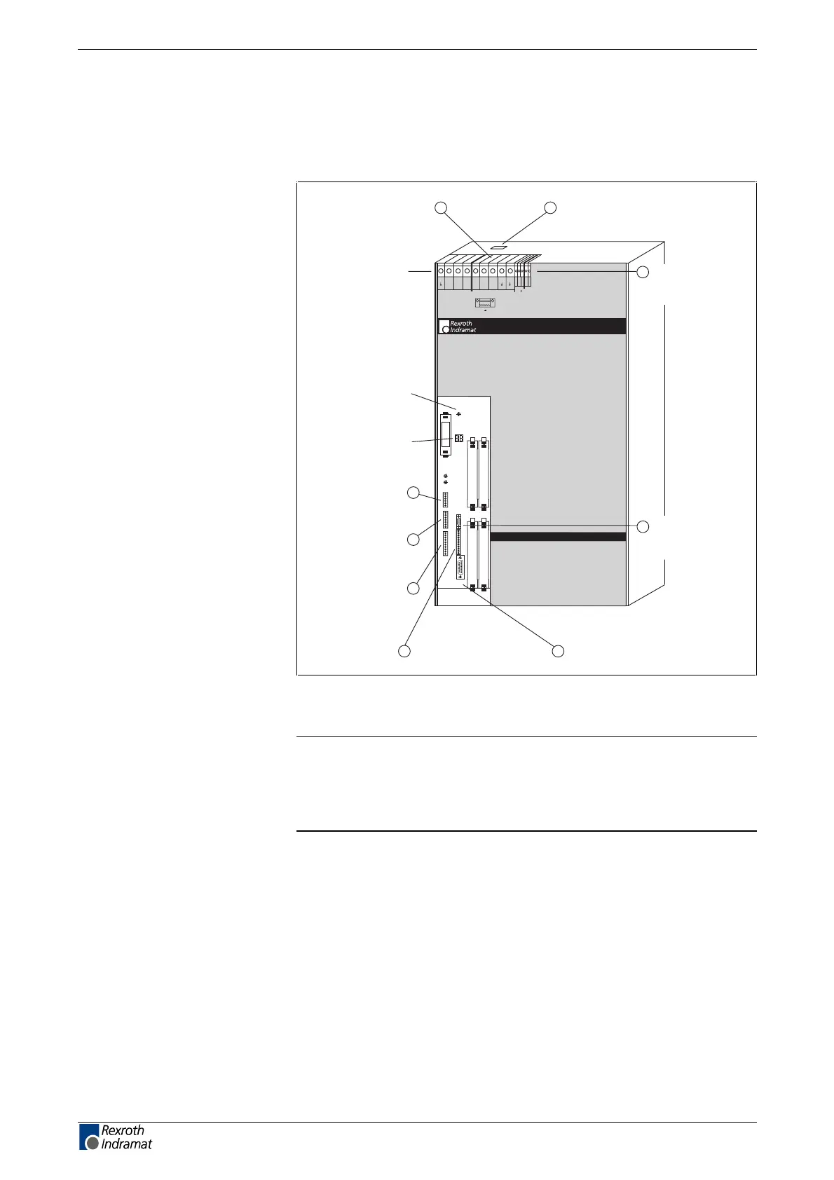
Reset key S1
status display,
warning and fault
messages (H1)
signal voltages
for measuring and
testing (X8)
analog measuring outputs
AK1, AK2, (X3)
signal outputs
Bb1, UD, TVW,
K1NO, K1NC (X7)
mains connection X5
motor power
connection X5
connection X6 for:
• motor temperature monitoring
• motor holding brake
connection for:
• control voltage
• option terminals X10
control inputs
ON, OFF (X9)
RS 232 interface for
VT-100 Terminal or
PC (X2)
motor feedback
connection (X4)
1
2
3
4
5
76
6
8
Fig. 6-1: Front of unit DKR02/DKR03 with connections labeled, names and
explanations
Note: Except for terminal connectors X5, X6 and X10 the
arrangement of the connections on DKR04 devices
corresponds to the arrangement on DKR02/DKR03 devices. In
case of DKR04 devices these terminal connectors are situated
at the bottom side of the device.
LSA Control S.L. www.lsa-control.com comercial@lsa-control.com (+34) 960 62 43 01