DKR Drive Controllers Planning the electrical connections 6-3
DOK-DIAX03-DKR********-PR02-EN-P
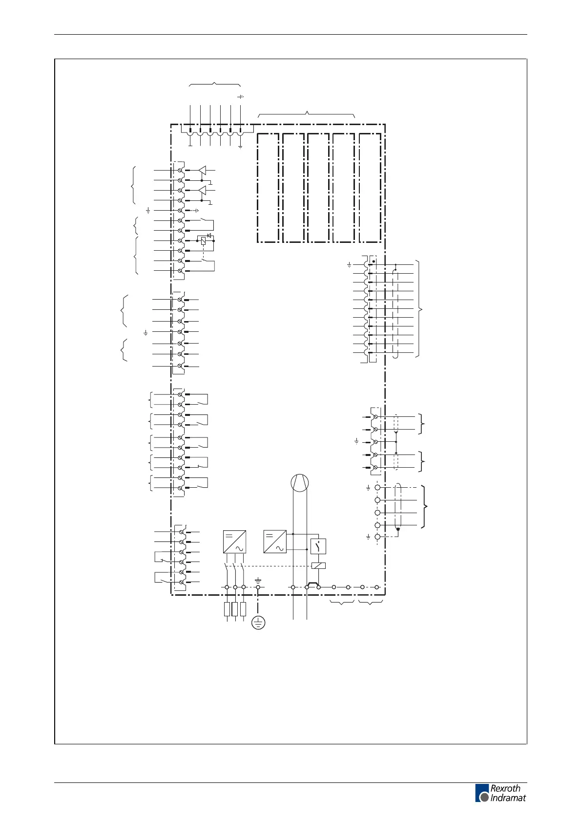
encoder interface:
connection of the DSF
encoder (digital servo
feedback)
APDKR
1
2
3
4
5
10
0VM
TxDTxD
RxDRxD
RTSRTS
X2
CTSCTS
1
2
3
4
5
6
7
8
9
10
11
AK1
0 VM
AK2
0 VM
Bb
Bb
AS+
AS-
ASQ
ASQ
X3
analoge
diagnostics
outputs
start inhibit
+15 VM
0 VM
-15 VM
+24VL
0VL
n/c
1
2
3
4
5
6
7
command interface card
aux. plug-in module U2
motor feedback connection
if motor feedback is not DSF
auxiliary plug-in module
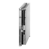
Digital compact
drive controller
DKR
A3
A2
A1
X6
X5
1
8
15
7
14
12
10
3
9
2
4
SDO
SDI
SCL
FS
U
G
Cos+ (B+)
Cos- (B-)
Sin+ (A+)
Sin- (A-)
0 V
M
X4
TM+
TM-
BR
0V
B
RS 232
interface
connecting the optional
plug-in mudules as per
the relvant diagrams
U1
U5
software module DSM
X8
U3
U4
1
2
3
4
5
3 x AC 400 … 480 V, 50…60 Hz
grounded mains
N L K
control voltage
AC 230 V, 50…60 Hz
L1 L2 L3
F1
X5
L1L2 L3
B1 B2
load with
50 mA
power
feed
control
voltage
infeed
K1
K1
1
2
3
4
5
6
ON
OFF
X9
1
2
3
4
5
6
7
8
9
10
acknowledge
power off
ready for power
temperature
prewarning
Bb1
UD
TVW
K1NC
K1NO
X7
blower
(max. 2 A)
X10
load with
2 A minus
holding brake
current
ready for
power
DC bus voltage o.k.
no error
DC bus voltage
500...600 V
+ -
R1 R2
+ -
bleeder connection
(only with DKR04.1-Wxxx-E)
motor connection
motor holding brake
temperature
monitoring
inhibit regeneration
of energy
auxiliary plug-in module
acknowledge
power on
Fig. 6-2: Connection allocations
LSA Control S.L. www.lsa-control.com comercial@lsa-control.com (+34) 960 62 43 01